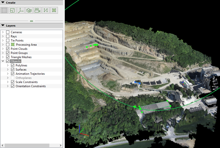
The Objects layer contains the following sub-layers:
- Polylines: Contains the list of polylines added to the project. A Polyline object is a continuous line composed of one or more sub-lines. It is created by specifying the vertices of each line. For more information about the concept of polyline: What is... (a densified point cloud? an orthomosaic? etc.).
- Surfaces: Contains the list of surfaces added to the project. A Surface object can be used to define planar areas such as a road, the roof of a building, etc. It can also be used to correct the DSM to generate a better orthomosaic on these surfaces and to correct the visual aspect of the 3D Textured Mesh removing noise or filling areas.
- Animation Trajectories: Contains the list of Animation Trajectories added to the project. The animation Trajectories consist of waypoints that define the path for an imaginary camera that records the scene.
- Orthoplanes: Contains the list of Orthoplanes added to the project. The Orthoplane is a tool to create one or several orthophotos of arbitrary areas of the model without having any impact / modifications in the model.
- Scale Constraints: Contains the list of Scale Constraints added to the project. The Scale Constraint is a line with known real Cartesian distance between 2 points, allowing to set up a local scale of the model.
- Orientation Constraints: Contains the list of Orientation Constraints added to the project. The Orientation Constraints is a line that represents a known axis, allowing to set up an local orientation of the model.
Polylines
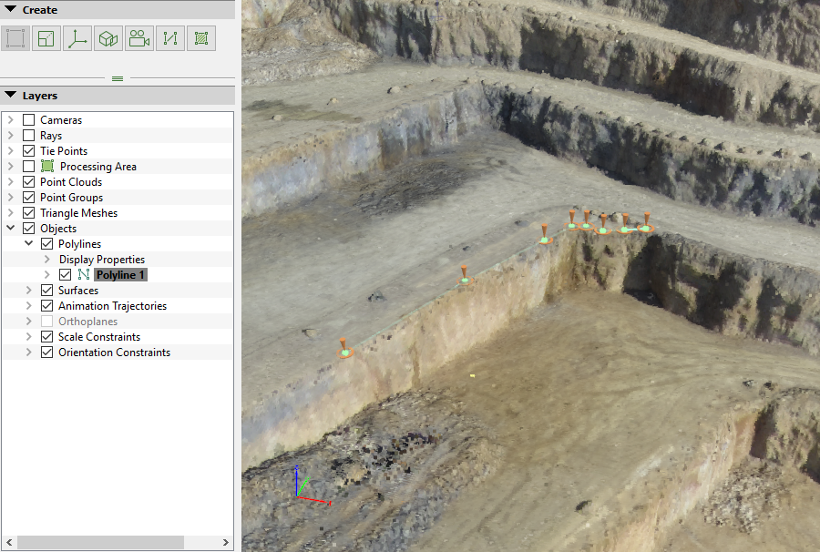
Contains the list of polylines added to the project. A Polyline object is a continuous line composed of one or more sub-lines. It is created by specifying the vertices of each line. For more information about the concept of Polyline: What is... (a densified point cloud? an orthomosaic? etc.).
The Polylines layer has the following structure:
- Display Properties: This layer allows the user to edit the display properties all the polylines.
- Vertex Color: Color of the spheres that represent the vertices of the polylines.
- Vertex Radius: Radius of the spheres that represent the vertices of the polylines.
- Line Color: Color of the lines between the vertices of the polylines.
- Line Width: Width of the lines defining the polylines.
- List of Polylines.
By right-clicking on the Polylines sub-layer, a context menu with the following options appears:
- New Polyline: Allows the user to draw a new polyline. For step by step instructions: How to draw a Polyline in the rayCloud.
- Export All Polylines: Opens the Export pop-up that allows to export the corresponding components from the polyline into a file.
The following file formats can be selected for export:Important: A Polyline is composed of lines and vertices to which Manual Tie Points are associated. The lines and vertices of the Polylines are exported. - AutoCAD DFX (.dfx).
- ESRI Shapefiles (.shp).
- Keyhole Markup Language (.kml).
- Microstation DGN (.dgn).
Surfaces
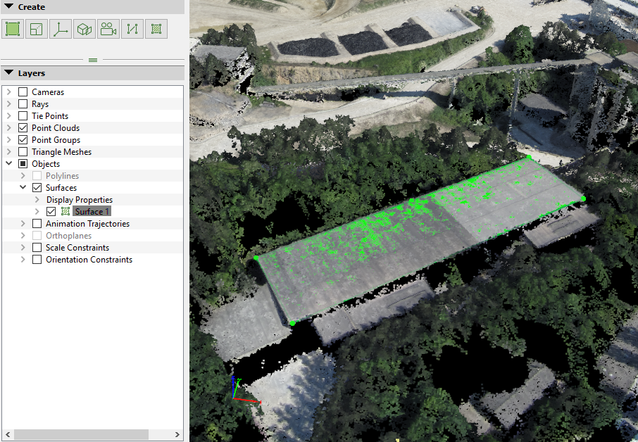
Contains the list of surfaces added to the project. A Surface object can be used to define planar areas such as a road, the roof of a building, etc. It can also be used to correct the DSM to generate a better orthomosaic on these surfaces and to correct the visual aspect of the 3D Textured Mesh removing noise or filling areas.
The Surfaces layer has the following structure:
- Display Properties: This layer allows the user to edit the display properties for all the surfaces.
- Color: Color of the base of the surfaces.
- Shader: Specifies the way each triangle of the base surfaces is colored. The color is related to the 3D position of each triangle. 2 ways of coloring the triangles are available:
- Monochrome: Selected by default. The triangles are colored with a color-to-black scale depending on the angle with respect to a virtual sun positioned in the north-east at 45 degrees from the horizon. It uses the color selected above.
- Color: The triangles are colored with an RGB scale. The color of a triangle depends on the angle with respect to 3 virtual suns with Red, Green, and Blue illumination. The color of each triangle is the combination of the light received by the 3 virtual suns. This shader gives a slope map if the model is looked at from the top. It gives information about the orientation of each surface.
- Vertex Color: Color of the spheres that represent the vertices of the surfaces.
- Vertex Radius: Radius of the spheres that represent the vertices of the surfaces.
- Line Color: Color of the lines between the vertices of the surfaces.
- Line Width: Width of the line defining the surface areas.
- Base: View/hide the base of the surfaces.
- List of Surfaces.
By right-clicking on the Surfaces sub-layer, a context menu with the following options appears:
- New Surface: Allows the user to draw a new surface. For step by step instructions: How to draw a Surface in the rayCloud.
- Export All Surfaces: Opens the Export pop-up that allows to export the corresponding components from the surface into a file.
The following file formats can be selected for export:Important: A Surface is composed of a surface mesh and vertices to which Manual Tie Points are associated. The vertices and the surface mesh of the Surfaces are exported. - AutoCad DFX (.dfx).
- ESRI Shapefiles (.shp).
- Keyhole Markup Language (.kml).
- Microstation DGN (.dgn).
List of objects
On the left of the object name, there is an icon indicating the type of the object:
 Polyline
 Surface
By right-clicking on a specific object's layer, a context menu with the following options appears:
- Insert Vertices: (only available for Polylines) Insert vertices on the line between existing vertices of the object.
- Rename: Rename the object.
- Export: Opens the Export pop-up that allows the user to export the corresponding components from the selected object into a file.
The following file formats can be selected for export:Important:- A Polyline is composed of lines and vertices to which Manual Tie Points are associated. The vertices and lines of the Polyline will be exported.
- A Surface is composed of a surface mesh and vertices to which Manual Tie Points are associated. The vertices and the surface mesh of the Surface will be exported.
- AutoCad DFX (.dfx).
- ESRI Shapefiles (.shp).
- Keyhole Markup Language (.kml).
- Microstation DGN (.dgn).
- Remove: Removes the selected object.
Animation Trajectories
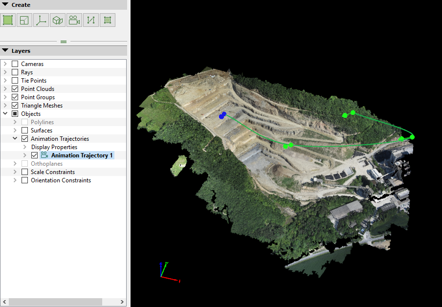
Contains the list of Animation Trajectories added to the project. The Animation Trajectories consist of waypoints that define the path for an imaginary camera that records the scene.
The Animation Trajectories layer has the following structure:
- Display Properties: Displays properties of the corresponding objects. The properties that can be edited are:
- Start Vertex Color: Color of the spheres that represent the first waypoints.
- Vertex Color: Color of the spheres that represent the waypoints.
- Vertex Radius: Radius of the spheres that represent the waypoints.
- Line Color: Color of the lines between waypoints.
- Line Width: Width of the line defining the path between waypoints.
- List of Animation Trajectories.
By right-clicking on the Animation Trajectories sub-layer, a context menu with the following options appears:
- New Video Animation Trajectory: Allows to create a new Animation Trajectory. For step by step instructions: How to create a Video Animation Trajectory in the rayCloud.
- Import...: Opens the Import Video Animation Trajectory pop-up that allows to import Animation Trajectories created previously with PIX4Dmapper for the same area of study or created manually.
For step by step instructions about how to import an Animation Trajectory to the rayCloud: How to import an Animation Trajectory to the rayCloud.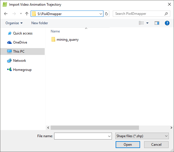
Contains the sections:
- Navigation window: Used to search for and select the file to be imported.
- File name: Displays the name of the selected file to be imported.
- Files of type: Displays the possible formats accepted for the input file: .csv and .txt are accepted.
And contains the action buttons:
- Open: Imports the selected file.
- Cancel: Does not import the animation and exits the pop-up.
Important: Manually created Animation Trajectories must have the same format and extension than files generated when exporting an Animation Trajectory with Pix4D.
List of Animation Trajectories
On the left of the object name, there is an icon indicating the type of the object:
 Animation Trajectory
By right-clicking a specific object's layer, a context menu with the following options appears:
- Rename: Renames the object.
- Remove: Removes the selected object.
- Export...: Opens the Export Video Animation Trajectory pop-up that allows to export the selected Animation Trajectory.
For step by step instructions about how to export an Animation Trajectory with the rayCloud: How to export an Animation Trajectory with the rayCloud.
Contains the action buttons:
- Save: Confirms the path and name to export the animation and opens the Video Animation Trajectory File Parameters pop-up:
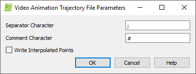
Contains the options: - Separator Character: Character to be used as separator for the different information for each waypoint / interpolated Point:
Time [s], Position X, Position Y, Position Z, Rotation X, Rotation Y, Rotation Z.
Note: The default value for separator ";" in Microsoft Excel is read as Tab and will place each separated text in one column.- Comment Character: Character to be used as first character for the comment lines which includes information about the video animation options:
Name, Time computation, Interpolation, Max speed, Duration, Number of points, Distance unit of measure, Angle unit of measure. - Write Interpolated Points [m]: By default it is not selected. Only the video animation options, the created waypoints and its coordinates are stored. Select Write Interpolated Points [m] to store as well intermediate points between consecutive waypoints and select the Maximum distance between interpolated points. By default, the value is 1, and it will create one intermediate point per meter.
- OK: Exports the animation.
- Cancel: Does not export the animation and exits the pop-up.
- Help: Opens the PIX4Dmapper help.
Important: It is possible to export Animation Trajectories as CSV files which can be opened with any text editor or spreadsheets editor. - Save: Confirms the path and name to export the animation and opens the Video Animation Trajectory File Parameters pop-up:
Orthoplanes
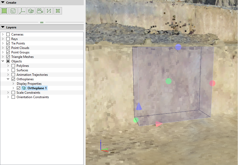
Contains the list of orthoplanes added to the project. An Orthoplane is a tool to create one or several orthophotos of arbitrary areas of the model without having any impact / modifications in the model.
The Orthoplanes layer has the following structure:
- Display properties: This layer allows the user to edit the display properties for all the orthoplanes.
- Color: Color of the top, bottom, and side planes that define the area.
- X Handle Color: Color of the X location arrow and X dimension sphere.
- Y Handle Color: Color of the Y location arrow and Y dimension sphere.
- Z Handle Color: Color of the Z location arrow and Z dimension sphere.
- Near Plane Edge Color: Color of the lines that define the surface that represents the origin of the projection.
- Far Plane Edge Color: Color of the lines that define the surface that represents the limit of the projection.
- List of Orthoplanes.
By right-clicking on the Orthoplanes sub-layer, a context menu with the following options appears:
- New Orthoplane: Allows to create a new 3D Orthoplane. For step by step instructions: How to draw a new orthoplane.
By right-clicking on a specific object's layer, a context menu with the following options appears:
- Rename: Renames the object.
- Remove: Removes the selected object.
Scale Constraints
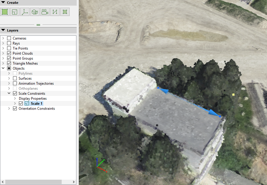
Contains the list of Scale Constraints added to the project. A Scale Constraints object is a line with known real Cartesian distance between 2 points, allowing to set up a local scale for the model.
The Scale Constraints layer has the following structure:
- Display Properties: This layer allows to edit the display properties for all the Scale Constraints.
- Vertex Color: Color of the spheres that represent the vertices of the Scale Constraints.
- Vertex Radius: Radius of the spheres that represent the vertices of the Scale Constraints.
- Line Color: Color of the lines between the vertices of the Scale Constraints.
- Line Width: Width of the line defining the distance between vertices of the Scale Constraints.
- List of Scale Constraints.
By right-clicking on the Scale Constraints sub-layer, a context menu with the following options appears:
- New Scale Constraint: Allows the user to create a new Scale Constraint. For step by step instructions: How to scale a project.
By right-clicking on a specific object's layer, a context menu with the following options appears:
- Remove: Removes the selected object.
Orientation Constraints
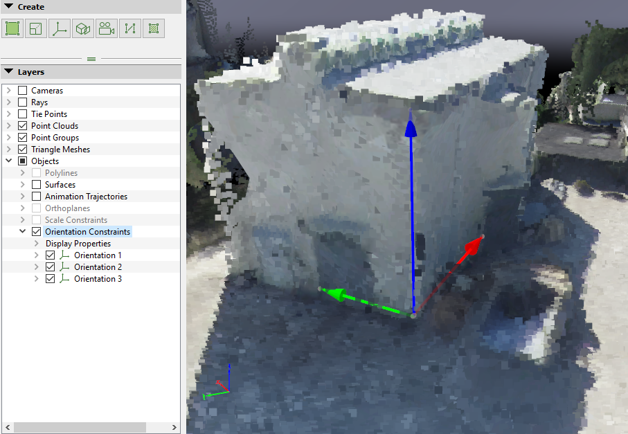
Contains the list of Orientation Constraints added to the project. An Orientation Constraints object is a line that represents a known axis, allowing to set up an local orientation for the model.
The Orientation Constraints layer has the following structure:
- Display properties: This layer allows the user to edit the display properties for all the Scale Constraints.
- Vertex Color: Color of the spheres that represent the vertices of the Orientation Constraints.
- Vertex Radius: Radius of the spheres that represent the vertices of the Orientation Constraints.
- Line Width: Width of the line defining the Orientation Constraints.
- List of Orientation Constraints.
By right-clicking on the Orientation Constraints sub-layer, a context menu with the following options appears:
- New Orientation Constraint: Allows the user to create a new 3D Orientation Constraint. For step by step instructions: How to orient a project.
By right-clicking on a specific object's layer, a context menu with the following options appears:
- Remove: Removes the selected object.