This article explains in detail how to draw a new orthoplane in PIX4Dmapper.
- An orthoplane can be drawn after step 1. Initial Processing has been completed.
- An orthoplane can only be generated after step 2. Point Cloud and Mesh has been completed.
In order to draw a new orthoplane in the rayCloud:
1. On the menu bar, click View > rayCloud.
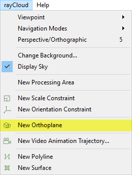
2. On the menu bar, click rayCloud > New Orthoplane.
3. In the 3D View, an orthoplane box appears beside the mouse. Left-click to place the box on a 3D point.
4. Adjust the orthoplane box so that it is parallel to the object (the facade of a building, the slope of a hill, etc.):
- Drag the arrows of the orthoplane box to move it and place it at the desired location. Drag the:
- Red arrow to move it towards the X direction.
- Green arrow to move it towards the Y direction.
- Blue arrow to move it towards the Z direction.
Or use the Position (X,Y,Z) options of the right sidebar: Menu View > rayCloud > Right sidebar > Objects.
- Drag the spheres of the orthoplane box to resize it. Drag the:
- Red sphere to resize the X length.
- Green sphere to resize the Y length.
- Blue sphere to resize the Z length.
Or use the Width, Height, Clipping Distance options of the right sidebar: Menu View > rayCloud > Right sidebar > Objects.
- Use the Orientation (Yaw, Pitch, Roll) options of the right sidebar to rotate the orthoplane box: Menu View > rayCloud > Right sidebar > Objects.
5. (optional) Click Flip to change the orientation and direction of the orthoplane.
6. (optional) If at least one surface object is drawn (How to draw a Surface in the rayCloud), click Align to align the orthoplane with an existing surface. (Select the desired surface from the drop-down list).
7. Click Apply to save the changes made under the Properties section of the right sidebar.
