N THIS ARTICLE
Setting up a project Log in
 Create new project
 Import Tie points
 Coordinate Reference System
 Image Coordinate Reference systemGCPs Coordinate Reference System
 Project coordinate system
 Calibration
![]() Gaussian splats & point cloud
Gaussian splats & point cloud Dense point cloud
 Mesh
Mesh DSM
DSM Orthomosaic
 Locate the export folder
Video tutorials
|
Introduction to the PIX4Dmatic interface
|
How to process aerial imagery with PIX4Dmatic
|
|
How to process PIX4Dcatch data with PIX4Dmatic
|
|
Setting up a project
The first step in PIX4Dmatic is setting up the project, defining the required parameters, and adding the necessary data before moving on to processing.
Log in
Sign-up for a Pix4D account or use the existing Pix4D account to log in to the software.
- Click
 icon or Log in on the top right side of the screen.
 - Enter the Email and click Continue.
- Enter the Password and click Log in.
Create new project
New projects in PIX4Dmatic can be created by dragging and dropping images or image folders on the home screen, using the menu bar, or the Ctrl + N (⌘ + N) shortcut.
Drag and drop input files
- Drag and drop images or image folders on the home screen.
- Specify the Project name, the Path of the project and the project Coordinate reference system (CRS).
- Click Start.

A new project has been created and is ready for processing. To import additional input files use the File menu on the top left or drag and drop them on the screen.
For more information: Create a project - PIX4Dmatic
Import Tie points (GCPs and CPs)
Adding and marking Tie points (Ground control points (GCPs) and Checkpoints (CPs)) in a project is optional but recommended for maintaining and validating the absolute accuracy of a project.
There are three methods to import a tie point .csv or .txt file into PIX4Dmatic. One is accessible through the File tab in the main header, and the others are accessible from the Tie Points panel.

- [1] Go to the Menu bar and select File > Import > GCPs... to select the GCP file.
- Click the
 Tie points (0) tab on the lower right of the screen to expand the tab.
 - [2] Drag and drop the GCP file, or Select from disk to specify the GCP file.
- [3]Click the dropdown menu
 and select
  Import GCPs...
 - Select the tie point file.
Tie points can be imported and marked at different stages:
- Before the Calibration step: This requires more manual work as the position of Tie Points on images is not precise as it is determined only based on the initial image geolocation and orientation. However, marking the Tie Points before processing can eliminate the need for reprocessing or reoptimizing the Calibrate step.
- After the Calibration step: The position of Tie Points on images is more precise as external and internal camera parameters are calculated. However, you will need to reprocess or reoptimize the Calibration step.
For more information on Tie points: Tie points - PIX4Dmatic
For more information on how to mark Tie points: Mark Tie points - PIX4Dmatic
Coordinate Reference System
After importing the images and the Tie points, the Coordinate Reference System (CRS) must be set. PIX4Dmatic allows setting the CRS of the Images, the GCPs, and the Project.
Image coordinate reference system
PIX4Dmatic allows the image coordinate system to be manually set or edited.
To edit the image horizontal or vertical coordinate systems, click on the edit icon ![]() in the lower right corner of the screen where the Cameras tab is.
in the lower right corner of the screen where the Cameras tab is.

After clicking on the edit icon, the Set image coordinate reference system (CRS) dialog box will open.

Unless a camera is in the PIX4Dmatic camera database or the images have the correct XMP tags, the default image coordinate system is WGS84 (EPSG: 4326) for the horizontal and EGM96 (EPSG: 5773) for the vertical.
GCPs coordinate reference system
Both the horizontal coordinate system and the vertical coordinate system can be defined in the Tie Points table:

The GCP coordinate reference system (CRS) window will pop up.
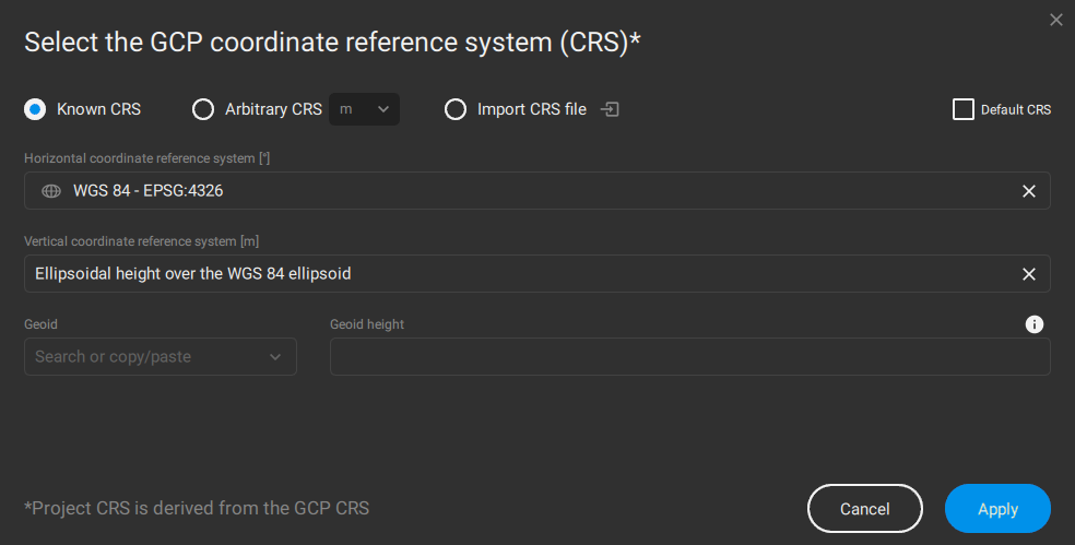
To select the horizontal coordinate reference system:
- In the Horizontal coordinate reference system dialog, search or copy-paste for either:
- The name of the coordinate reference system.
-
- The EPSG code of the coordinate system.
To select the vertical coordinate reference system:
- In the Vertical coordinate reference system dialog, search or copy-paste for either:
- The name of the coordinate reference system.
-
- The EPSG code of the coordinate system.
- (Optional) Geoid: If the selected vertical coordinate system supports geoids and the geoid model is available in the PIX4Dmatic database, select the geoid model in the drop-down list.
- (Optional) Geoid height: If the selected vertical coordinate system supports geoids but the geoid model is not available in the PIX4Dmatic database, enter the value of the geoid height at that location.
For more information and the list of supported geoids, please see How to use Geoids in PIX4Dmatic.
Project coordinate reference system
The horizontal and vertical coordinate reference systems for the project are determined by either the geolocation data of the imported images or the selected GCP coordinate reference system:
- If the GCPs coordinate system is not defined, PIX4Dmatic will automatically set the project’s coordinate system to the WGS84/UTM zone corresponding to the image's geolocation. The vertical coordinate system will use ellipsoidal heights.
- If the GCP coordinate system is defined, the project will adopt the same coordinate system as the GCPs. However, if the GCPs are in geographic coordinates, the output coordinate system will default to the corresponding WGS84/UTM zone.

Processing options
Once the project setup is complete, the next step is processing. PIX4Dmatic offers a range of configurable options for each processing stage, from image calibration to the generation of Digital Surface Models (DSM) and orthomosaics, tailored to meet various project requirements. PIX4Dmatic includes three default processing templates:
- Nadir
- Oblique
- PIX4Dcatch
Users can also create custom processing templates to save, reuse, and share predefined settings for consistent workflows. For more information: Custom Processing templates - PIX4Dmatic.
Calibration
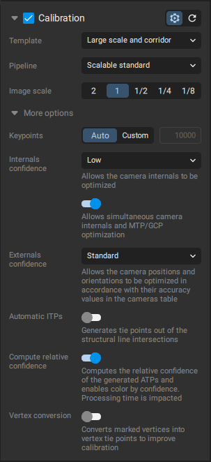
Calibration is the first step in processing a dataset and establishes the foundation for subsequent steps. The default settings are typically the best starting point.
For more information: Calibration - PIX4Dmatic
For PIX4Dcatch projects: How to process PIX4Dcatch datasets - PIX4Dmatic
Gaussian splas & point cloud
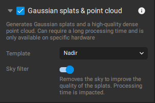
Gaussian splatting is a novel technique for 3D scene reconstruction and rendering that represents a scene as a collection of 3D Gaussians rather than traditional meshes or point clouds. It allows for highly detailed 3D models with photorealistic rendering.
For more information: Gaussian splatting - PIX4Dmatic
Dense point cloud
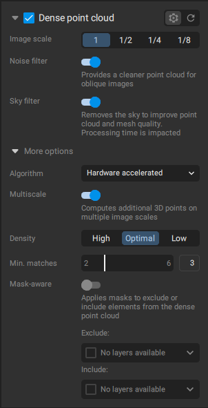
A dense point cloud consists of a collection of points distributed throughout a 3D space, representing the area of interest. The Dense Point Cloud step provides a 3D representation of reality, serving as the foundation for generating other 2D and 3D outputs in PIX4Dmatic.
For more information: Dense point cloud - PIX4Dmatic
AI tool
AI tool: This step computes the necessary data to enable the object selection tool and is required only once.

For more information: Object selection tool - PIX4Dmatic.
Mesh
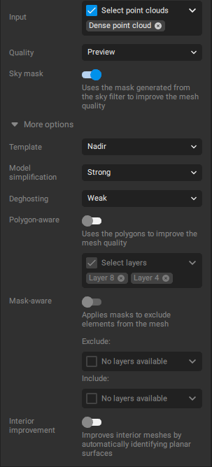
The Mesh step is created directly from the dense point cloud and is not mandatory for every project. Furthermore, generating a mesh is not required to produce the Digital Surface Model or Orthomosaic.
For more information: Mesh - PIX4Dmatic
DSM
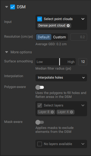
A Digital Surface Model (DSM) is a 2D representation of elevation, capturing both natural and artificial features within the area of interest. The DSM step is essential for generating the orthomosaic, thus any adjustments to DSM processing settings will affect the orthomosaic. This step defines the resolution, enables surface smoothing, and allows interpolation for DSM creation.
For more information: DSM - PIX4Dmatic
Orthomosaic
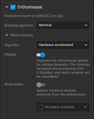
An Orthomosaic is a highly detailed and realistic 2D representation of reality generated by combining individual images. The Orthomosaic step is generated directly from the Digital Surface Model (DSM), thus any errors or gaps in the DSM will also be present in the orthomosaic.
For more information: Orthomosaic - PIX4Dmatic
Outputs
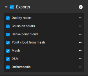
Once processing is complete, the Exports window in PIX4Dmatic provides the selection of the following outputs:
- Quality Report
- Gaussian splats
- Dense point cloud
- Point cloud from mesh
- Mesh
- Digital Surface Model (DSM)
- Orthomosaic
Locate the export folder
To access the outputs, click on File and select Open project folder. The exported files can be found in the Exports folder.
For more information: Outputs - PIX4Dmatic