This article describes the feature options in each section of the Index Calculator tab in the Processing Options window.


Allows the user to change the processing options and outputs related to the Index Calculator. These are processed during step 3. DSM, Orthomosaic and Index.
These settings come in 5 sections:
- Radiometric Processing and Calibration: Allows the users to calibrate and correct the image reflectance, considering the illumination and sensor influence.
- Resolution: Allows the user to set the resolution as well as the downsampling method (if needed).
- Reflectance Map: Allows the user to decide if the Reflectance Map(s) will be generated while processing step 3. DSM, Orthomosaic and Index, and if the Tiles will be merged.
- Indices: Shows the list of indices either from the database or created by the user. Allows the user to select which indices are generated while processing step 3. DSM, Orthomosaic and Index. For the selected indices, the Index Map is saved as a GeoTIFF, the Index Map Grid as a .shp file, the Classes as a .shp file, and the Classes with color representation as a .jpg file.
- Export: Allows the user to select some desired outputs.

Radiometric Processing and Calibration
Allows the users to calibrate and correct the image reflectance, considering the illumination and sensor influence. It is possible to choose the type of radiometric correction to be done:
- No correction: no radiometric correction will be done
- Camera only: corrections will be applied to the parameters that are written in the EXIF metadata and relate to the camera (vignetting, dark current, ISO, etc...): Exif/Xmp tags required for radiometric correction for multispectral camera
- Camera and Sun Irradiance: corrections will be applied to the camera parameters (same as using the option Camera only) as well as for the sun irradiance information written in the XMP.Camera.Irradiance EXIF tag.
- Camera, Sun Irradiance and Sun angle: corrections will be applied to the camera parameters and the sun irradiance information (same as using the option Camera and Sun Irradiance) as well as to take into account the sun position. This option should only be chosen for flights that were done in clear-sky conditions.
- Camera, Sun Irradiance and Sun angle using DLS IMU: Same as the previous one but does not need to have a fixed position and angle between the camera and DLS sensor. The orientation is tagged from the IMU embedded in the sun sensor.
The camera used is displayed. Users can calibrate the sensor to perform an illumination adjustment in order to obtain more accurate reflectance values. If there are more than one camera model in the project, all the cameras will be listed in the Radiometric Processing and Calibration section.
The Calibrate button allows us to consider the information from a picture with a radiometric calibration target if such a target was used during the project. After clicking Calibrate for a camera model, the Radiometric Calibration pop-up appears:

The Radiometric Calibration pop-up has 2 sections:
- Image: The image section allows the user to browse the image that will be used for the radiometric calibration.
- Reflectance Factor: The Reflectance Factor section allows the user to set the reflectance values for the calibration target.
Image
In File Name, the Browse button, opens the Select a radiometric calibration image pop-up. This pop-up allows the user to select the image in which the radiometric calibration target appears.
When an image is browsed, the user can draw a region on the image that will define the radiometric calibration. The Reset button, resets the area drawn by the user.
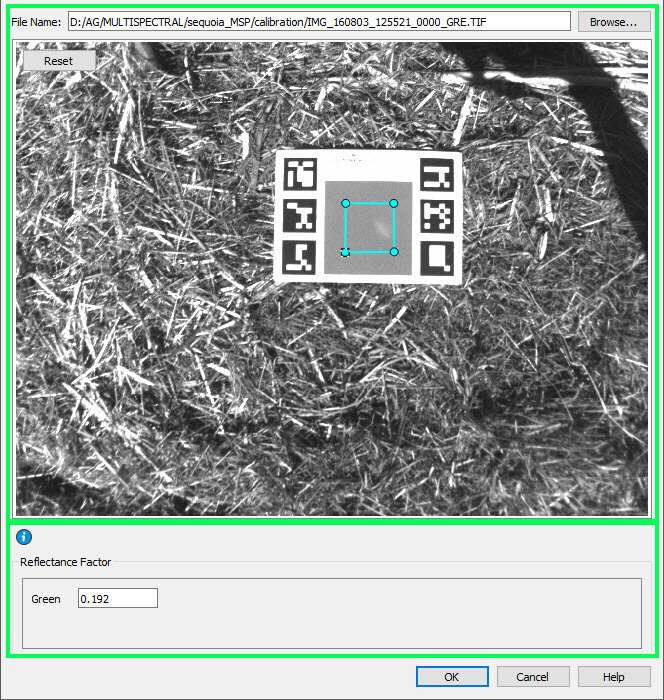
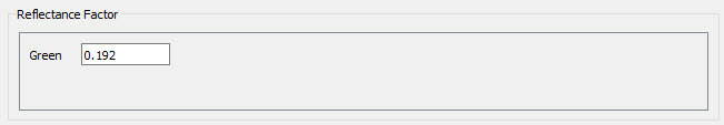
Reflectance Factor
In the Reflectance Factor section, the detected bands of the camera model appear. This section allows the user to type the reflectance values for the calibration target for the bands of the camera model selected.
For more information about the radiometric calibration target: Radiometric calibration target - PIX4Dmapper.
and the action buttons:
- OK: Confirms the radiometric calibration.
- Cancel: Does not save the radiometric calibration.
- Help: Opens the PIX4Dmapper help.
Resolution
Allows the user to set the resolution for the reflectance map. If a resolution lower than 1 GSD is chosen, the downsampling method can be chosen among the following options. Note that the window size will depend on the downsampling rate:
- Gaussian Average: Apply a Gaussian filter to the image.
- Fast Gaussian: This option performs the downsampling on the original images (hence does not produce a 1GSD reflectance map first), resulting in faster processing time.
- Average: The pixel takes the average value of the window around it.
- Median: The pixel takes the median value of the window around it.
- 75% Quantile: The pixel takes the value of the 75% quantile of the window around it.
- Minimum pixel: The pixel takes the minimal pixel value of the window around it.
- Maximum pixel: The pixel takes the maximal pixel value of the window around it.
Reflectance Map
Allows users to generate and save the Reflectance Map in GeoTIFF format.
- GeoTIFF: The Reflectance Map is generated and saved in GeoTIFF format during the step 3. DSM, Orthomosaic and Index.
- Merge Tiles: For most projects, the Reflectance Map is split into tiles where every tile is in GeoTIFF format. This option generates a single Reflectance Map file by merging all the individual tiles.
When this box is deselected, the merged Reflectance Map file is not generated, and users will only find smaller tiles in the result folder.
- Merge Tiles: For most projects, the Reflectance Map is split into tiles where every tile is in GeoTIFF format. This option generates a single Reflectance Map file by merging all the individual tiles.
Indices
Allows the user to select which indices are generated while processing step 3. DSM, Orthomosaic and Index (If in the section Reflectance Map, Geotiff is selected), and generates the Index Map Grid and the Classes for the selected indices. The resolution of the Index Map generated is the same as the Reflectance Map.
- Indices Box: All indices are displayed in the gray box with icons:
-
 : The index exists in the PIX4Dmapper index database. For more information about the PIX4Dmapper Index Database List: PIX4Dmapper Index Database List.
 -
 : The index was created / edited by the user in another project (on the same computer) that was closed and saved. :Edit, Add, and Delete Indices and Formulas in the Index Calculator - PIX4Dmapper.
 -
 : The index was created / edited by the user in this project: Edit, Add, and Delete Indices and Formulas in the Index Calculator - PIX4Dmapper.
Export
Allows the user to select some desired outputs:
- Index Values as Point Shapefiles (.shp): This map is generated while generating the Index Map. The Index Map Grid is generated by placing a grid in the Index Map. If a grid point lays on exactly 1 pixel, it takes the value of the pixel of the Index Map. If a point lays on several pixels, its value is interpolated with the values of the neighboring cells of the Index Map.
- Grid Size [unit/grid]: Defines the grid size. The default value is 200 cm/grid.
Note: The maximum value that can be entered is 10000.
- Index Values and Rates as Polygon Shapefiles (.shp): Allows the user to export the index values and rate regions as a .shp file.
- Grid Size [unit/grid]: Defines the grid size. The default value is 400 cm/grid.
Note: The maximal value that can be entered is 10000.