- The object information is displayed when an object is selected in the 3D View, or when an object is selected in the Layers section of the left sidebar.
Index > Interface > Menu View > rayCloud > Right sidebar
This article explains the objects (shortcut) found on the right sidebar of rayCloud in PIX4Dmapper.
Access: On the Menu bar, click View > rayCloud to open the rayCloud. The right sidebar is displayed on the right of the main window.
There are 7 type of objects:
Note: A Manual Tie Point is associated to each vertex of the objects. The Sidebar allows the user to mark these Manual Tie Points on the images. Each vertex that is marked in a least 2 images is taken into account in step 1. Initial Processing if it is started from scratch or if the reconstruction is re-optimized.
Polylines
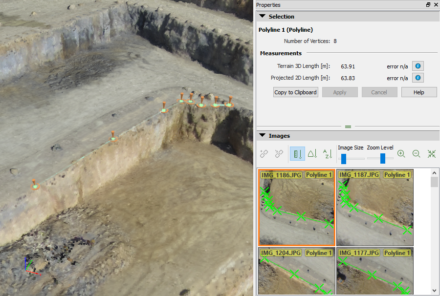
The following information is displayed:
- Object name (object type): The name of the Polyline and its type (Polyline).
- Number of Vertices: Number of vertices used to draw the Polyline.
- Measurements
- Terrain 3D length [units]: 3D length of the Polyline, taking into account the three coordinates of the vertices. For more information: Projected 2D length and terrain 3D length of polylines.
- Projected 2D length [units]: 2D length of the Polyline, taking into account the (X,Y) coordinates of the vertices. For more information: Projected 2D length and terrain 3D length of polylines.
Note: When the polyline is created, next to the measurements, "error n/a  " appears indicating that the measurement accuracy cannot be calculated until all the vertices of the polyline are marked on at least 2 images. For step by step instructions: How to edit Objects in the rayCloud.
" appears indicating that the measurement accuracy cannot be calculated until all the vertices of the polyline are marked on at least 2 images. For step by step instructions: How to edit Objects in the rayCloud.The direct access to:
- Copy to Clipboard: Copy the selected information to the clipboard that can be pasted into a text editor or spreadsheet by opening the destination file and pasting.
- Apply: This button is active when the image marks for the Manual Tie Points associated to the Polyline vertices have been modified, i.e. when a new image has been marked or when an existing mark has been updated or removed. When clicking this button, the new marks are taken into account and the 3D position of the corresponding vertices is recomputed.
- Cancel: This button is active when the image marks for the Manual Tie Points associated to the polyline vertices have been modified, i.e. when a new image has been marked or when an existing mark has been updated or removed. It cancels the modifications of the image marks.
- Help: Opens the PIX4Dmapper help.
The Images section: Displays the images where the object can be found. For more information: Menu View > rayCloud > Right sidebar > Images section.
For step by step instructions about how to draw a new Polyline: How to draw a Polyline in the rayCloud.
Surfaces
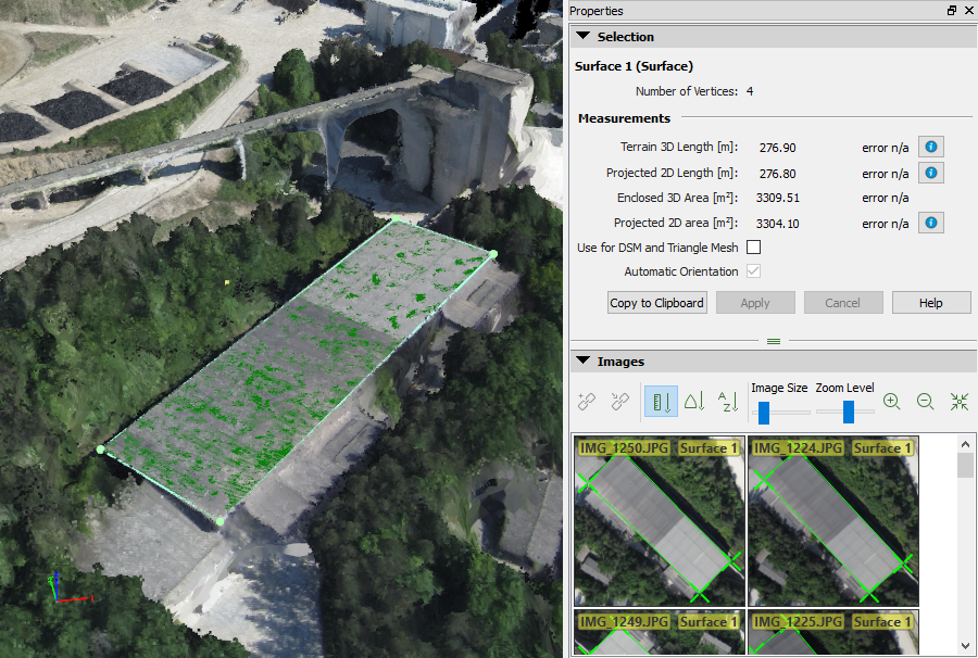
The following information is displayed:
- Object name (object type): The name of the Surface and its type (Surface).
- Number of Vertices: Number of vertices used to draw the object.
- Measurements
- Terrain 3D Length [units]: 3D length of the line that has been used to draw the Surface taking into account the three coordinates of the vertices. For more information: Projected 2D length and terrain 3D length of polylines.
- Projected 2D Length [units]: 2D length of the line that has been used to draw the Surface taking into account the (X,Y) coordinates of the vertices. For more information: Projected 2D length and terrain 3D length of polylines.
- Enclosed 3D Area [units2]: 3D area that is enclosed by this surface, taking into account the three coordinates of the vertices.
- Projected 2D Area [units2]: 2D area that is enclosed by this surface, taking into account the (X,Y) coordinates of the vertices.
Note: When the surface is created, next to the measurements, "error n/a  " appears indicating that the measurement accuracy cannot be calculated until all the vertices of the surface are marked on at least 2 images. For step by step instructions: How to edit Objects in the rayCloud.
" appears indicating that the measurement accuracy cannot be calculated until all the vertices of the surface are marked on at least 2 images. For step by step instructions: How to edit Objects in the rayCloud.Used for DSM and triangle Mesh: When this box is selected, the surface is used to improve the DSM model and the 3D textured Mesh. For more information: How to improve the 3D textured mesh.
Automatic: Selected by default. It uses the normals of the points covered by the surface to estimate the normal of the plane. If the checkbox is not selected, the sequence in which the surface vertices are drawn is used to define the normal of the plane. In this case, the surface should be drawn counterclockwise.
And the buttons:
- Copy to Clipboard: Copy the selected information to the clipboard that can be pasted into a text editor or spreadsheet by opening the destination file and pasting.
- Apply: This button is active when the image marks for the Manual Tie Points associated to the surface vertices have been modified, i.e. when a new image has been marked or when an existing mark has been updated or removed. When clicking on this button, the new marks are taken into account and the 3D position of the corresponding vertices is recomputed.
- Cancel: This button is active when the image marks for the Manual Tie Points associated to the surface vertices have been modified, i.e. when a new image has been marked or when an existing mark has been updated or removed. It cancels the modifications of the image marks.
- Help: Opens the PIX4Dmapper help.
The Images section: Displays the images where the object can be found. For more information: Menu View > rayCloud > Right sidebar > Images section.
For step by step instructions about how to draw a new Surface: How to draw a Surface in the rayCloud.
Animation Trajectories
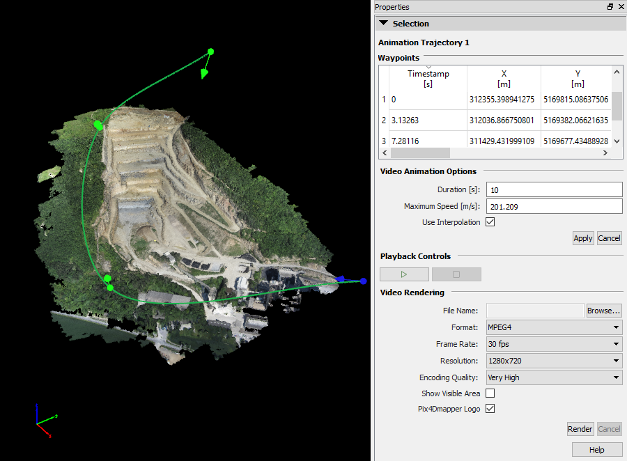
Under Selection in the main frame the name of the Animation trajectory and 4 sections appear:
And the button:
- Help: Opens the PIX4Dmapper knowledge base.
Waypoints
The following actions can be performed on the table:
- Inserting Waypoints: Right click on any cell and click on one of the followings:
- Insert Current Viewpoint as Waypoint Before Selection: Inserts the actual viewpoint in the 3D View as waypoint before the selected row (selected waypoint).
- Insert Current Viewpoint as Waypoint After Selection: Inserts the actual viewpoint in the 3D View as waypoint after the selected row (selected waypoint).
- Insert Displayed Computed Cameras Position as Waypoint Before Selection: Inserts ALL the cameras that are actually visible in the 3D View as waypoints before the selected row (selected waypoint) by placing them (if more than one camera is inserted, the order is defined considering the exif information from the cameras).
- Deleting Waypoints: Right click on any cell, and click on Remove Selected Waypoints.
- Editing Values: Double click on the cell and edit the value. Timestamp cannot be edited manually, the values can be changed by changing the Duration, Maximum Speed or selecting/unselecting the Use Interpolation checkbox.
The table has as many rows as there are waypoints in the Animation Trajectory. Each row displays information for one waypoint.
- Label: Name of the waypoint.
- Timestamp [s]. Time at which the animation passes through the waypoint.
- X coordinate [units]
- Y coordinate [units]
- Z coordinate [units]
- Omega (Rotation in X Axis) [degrees]
- Phi (Rotation in Y Axis) [degrees]
- Kappa (Rotation in Z Axis) [degrees]
Video Animation Options
This section allows the user to change the time of the animation and use or not use interpolation between waypoints:
- Duration [s]: Total length in seconds for the animation.
- Maximum Speed [m/s]: Maximum speed of the movement of the fly-trough camera in meters/second. The speed is not constant since the software recognizes changes in direction and orientation and reduces the speed in that sectors to allow smother camera movements.
- Use Interpolation: Ensures a smooth transitions between waypoints.
Note:
- If the Use Interpolation checkbox is NOT selected, the path between waypoints will be straight lines.
- If the Use Interpolation checkbox is selected, the path between waypoints will be curved lines. The angle of the curve is related to the angle between consecutive lines.
This section contains 2 action buttons:
- Apply: Saves the changes done in the sections Waypoints or Video Animation Options.
- Cancel: Reverts the changes to restore the saved Animation Trajectory.
Playback Controls
This sections allows to display the animation in the 3D View.
 Play animation
 Stop animation
Video Rendering
This sections allows to create a video file and set up different video rendering properties:
- File Name: Displays the path and the name where the video will be rendered and saved.
- Format: Video file format. The available options are: MPEG4 and MPEG2.
- Frame Rate: Frames per second to be stored in the video. The available options are: 24, 30 and 60 fps.
- Resolution: Total width and height of the video in pixels. The available options are: 800x600, 1024x768, 1280x720 and 1920x1080.
- Encoding Quality: Defines the pixel size within the video, the higher the encoding quality the higher definition
- Show Visible Area: Displays / does not display in the 3D View a frame allowing to see which part of the 3D View fits in the scene to be recorded according to the resolution. Elements outside the visible area do not appear in the recorded video
- PIX4Dmapper Logo: When rendering and creating the video, it displays/ does not display the PIX4Dmapper logo in the bottom right of the video.
This section contains 4 action buttons:
- Browse... : Opens the Save Video As window which allows to choose the video's folder.
- Render: Converts the animation Trajectory into a video, saved in the selected path and using the video properties selected.
- Cancel: Enabled while Rendering is in progress, allows to cancel the rendering of an Animation Trajectory into Video.
- Help: Opens the PIX4Dmapper knowledge base.
For step by step instructions about how to create an Animation Trajectory: How to create a Video Animation Trajectory in the rayCloud.
Orthoplanes
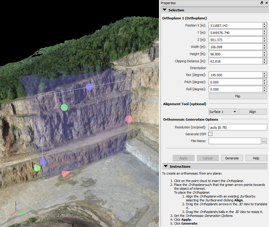
Under Selection in the main frame appears 3 sections:
- Object name (object type): The name of the Orthoplane and its type (Orthoplane).
- Position X [units]: Position in X of the reference corner with respect to the origin of the output coordinate system.
- Y [units]: Position in Y of the reference corner with respect to the origin of the output coordinate system.
- Z [units]: Position in Z of the reference corner with respect to the origin of the output coordinate system.
- Width [units]: Size in X of the orthoplane area in output coordinate system units.
- Height [units]: Size in Y of the orthoplane area in output coordinate system units.
- Clipping Distance [units]: Size in Z of the orthoplane area in output coordinate system units.
- Orientation: Defines the rotation of the orthoplane area with respect to the axes of the coordinate system.
- Yaw [degrees]: Rotation around the Y axis.
- Pitch [degrees]: Rotation around the X axis.
- Roll [degrees]: Rotation around the Z axis.
- Flip: Changes the orientation and direction of the projection.
- Alignment tool (optional): Allows the user to align the orthoplane with a Surface Object.
- Surface1: Allows the user to select the surface object to use for alignment.
- Align: Aligns the Orthoplane to the selected surface by using the perpendicular vector to the surface as direction of the projection and using the base of the surface as middle point of the Z of the Orthoplane.
- Orthomosaic Generation Options: Options related to the output files.
- Resolution [cm/pixel]: This value can be modified before generating the new Orthoplane mosaic and indicates the spatial resolution of the Orthomosaic.
- Generate DSM: When the checkbox is selected, a DSM file is generated with the Orthoplane Mosaic. Processing options are optimized for facades (sharp Surface Smoothing and Noise Filtering for the DSM filters, Raster DSM method set to Inverse Distance Weighting).
- File Name: Path where the Orthoplane and optionally the DSM will be stored.
- ...: Selects the path where the Orthoplane and optionally the DSM will be stored.
And the buttons:
- Apply: Enabled when there has been any change in the properties of the object. It applies the changes.
- Cancel: Cancels the changes in the properties since the last time that apply has been clicked.
- Generate: Generates the Orthomosaic and optionally the DSM for the selected orthoplane in the selected path.
- Help: Opens the PIX4Dmapper knowledge base.
The Instructions section displays instructions about how to draw a new Orthoplane.
For step by step instructions about how to draw a new Orthoplane: How to draw a new orthoplane.
Scale Constraints
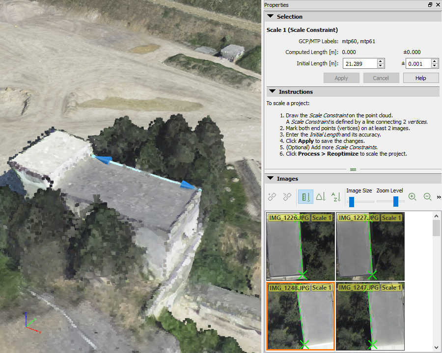
Contains 3 sections:
- Selection
- Instructions
- Images
Under Selection in the main frame appears:
- Object name (object type): The name of the Scale and its type (Scale Constraint).
- GCP/MTP Labels: When creating a Scale Constraint, the vertices of the line representing the scale constraint are associated to Manual Tie Points. This label displays the names of the Manual Tie Points associated to the object.
- Computed Length [units]: Length measured in the 3D model. The Computed Length Error is given by the difference between the Computed Length and the Initial Length.
- Initial Length [units]: Length measured in the field representing the real length of the scale constraint. The accuracy of the Initial Length is the accuracy of the measurements in the field.
And the buttons:
- Apply: Enabled when there has been any change in the properties of the object or a new marking in the images. It applies the changes.
- Cancel: Cancel the changes in the properties or in the marking since the last time that apply has been clicked.
- Help: Opens the PIX4Dmapper help.
The Instructions section: Displays instructions about how to draw a new Scale Constraint.
The Images section: Displays the images in which the object is visible. For more information: Menu View > rayCloud > Right sidebar > Images section.
For step by step instructions about how to draw a new Scale Constraint: How to scale a project.
Orientation Constaints
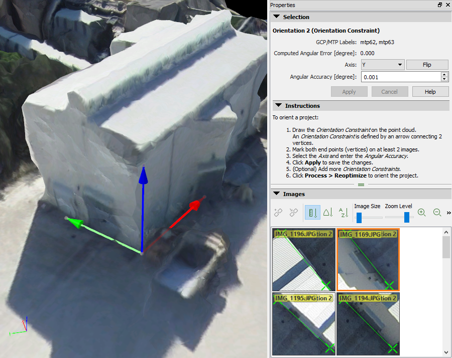
Contains 3 sections:
- Selection
- Instructions
- Images
Under Selection in the main frame appears:
- Object name (object type): The name of the Orientation and its type (Orientation Constraint).
- GCP/MTP Labels: When creating an Orientation Constraint, the vertices of the arrow representing the scale constraint are associated to Manual Tie Points. This label displays the names of the Manual Tie Points associated to the object.
- Computed Angular Error [degree]: Angular difference between the computed axis and the axis that was drawn.
- Axis: Name of the axis that the Orientation Constraint represents.
- Flip: Changes the direction of the Orientation by rotating it by 180°.
- Angular Accuracy [degree]: Angular accuracy of the measurements in the field.
And the buttons:
- Apply: Enabled when there has been any change in the properties of the object or a new marking in the images has been done. It applies the changes.
- Cancel: Cancels the changes in the properties or in the marking since the last time that apply has been clicked.
- Help: Opens the PIX4Dmapper help.
The Instructions section: Displays instructions to draw a new Orientation Constraint. For more information, How to orient a project.
The Images section: Displays the images where the object can be found. For more information: Menu View > rayCloud > Right sidebar > Images section.
Index > Interface > Menu View > rayCloud > Right sidebar