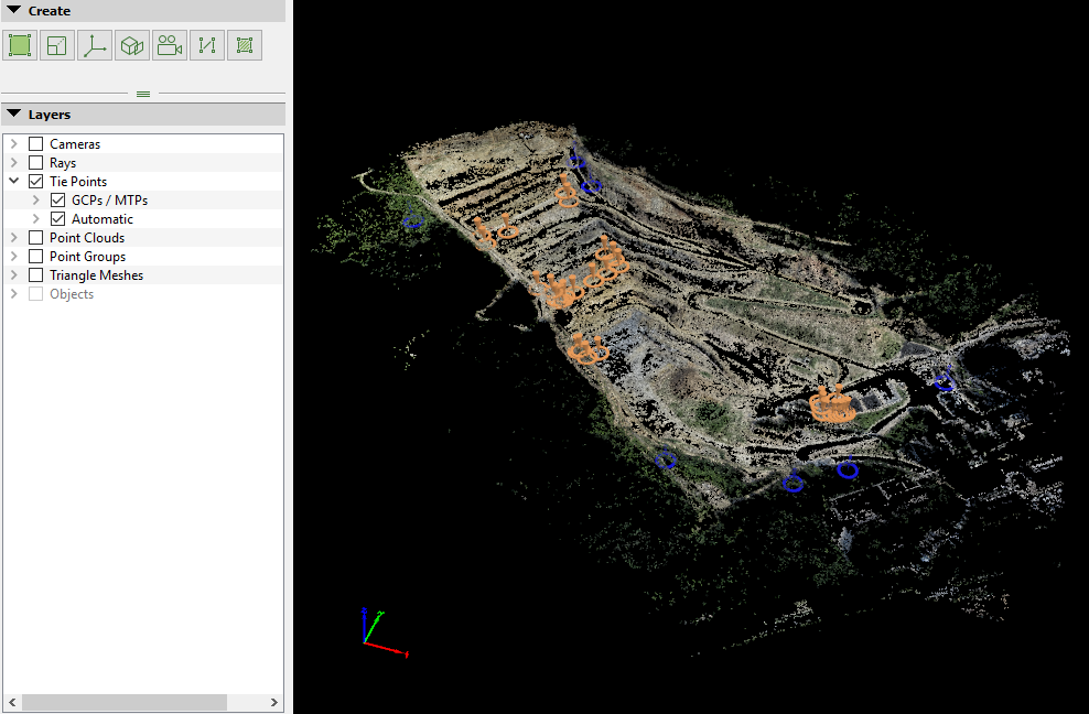
Access: On the Menu bar, click
View > rayCloud to open the rayCloud. The
Layers section in the left sidebar is displayed on the left of the main window.
The Tie Points layer contains the following sub-layers:
- GCPs/MTPs: All the Manual Tie Points, 2D GCPs, 3D GCPs, and Check Points of the project.
- Automatic: The Automatic Tie Points computed during step 1. Initial Processing. Only Automatic Tie Points visible in at least 3 images are displayed.
The GCPs/MTPs layer has the following structure:
- Display Properties: Displays properties of all Manual Tie Points and GCPs.
- Computed Position: View/hide the points optimized position.
- Minimum Pixel Size: Defines the size of the points' computed positions on the screen (not the real size of the points with respect to the model). This property allows the points to be visible both when visualizing the model from very close and from very far. When the zoom level is above the given zoom level defined by the Minimum size property, the points keep the same size on the screen independently from the zoom level. When zooming in closer to the model, below the zoom level defined by the Minimum size property, the size of the points on the screen will increase each time the user zooms in so that the points remain visible even if the view is close to the model.
- Minimum Physical Size: Defines the minimum physical size of the points in the 3D View. This defines the zoom level below which the points need to be displayed with their real size with respect to the model so that the points remain visible even when zooming in very close to the model.
- Marked Color: Cross color of the points' computed positions for points marked on at least 2 images.
- Non marked color: Cross color of the points' computed positions for points marked in less than 2 images.
- Initial Position: View/hide the points' initial positions (this property affects only the GCPs and Check points).
- Minimum Pixel Size: Defines the size of the points' initial positions on the screen (not the real size of the points with respect to the model). This property allows the points to be visible both when visualizing the model from very close and from very far. When the zoom level is above the given zoom level defined by the Minimum size property, the points keep the same size on the screen independently from the zoom level. When zooming in closer to the model, below the zoom level defined by the Minimum size property, the size of the points on the screen will increase each time zooming in so that the closer to the model the view gets, the points remain visible.
- Minimum Physical Size: Defines the physical minimum size of the points on the 3D View. This defines the zoom level below which the points need to be displayed with its real size with respect to the model so that the points remain visible even when zooming in very close to the model.
- Color: Cross color of the points' initial positions for GCPs.
- Checkpoint Color: Cross color of the points' initial positions for Check Points.
- Position error: View/hide the line between the points' initial and computed positions (this property affects only the GCPs and Check points).
- Color: Color for the line between the points' initial and computed positions (this property affects only the GCPs and Check points).
- Show Error Ellipsoid: View/hide the ellipsoid formed by the theoretical error. For more information: What is the Theoretical Error S(X,Y,Z) of a computed 3D point?.
- Color: Color for the error ellipsoid.
- Physical Size Scale: Defines the minimum physical size of the ellipsoid on the 3D View. This defines the zoom level below which the ellipsoid need to be displayed with their real size with respect to the model so that the ellipsoid remain visible even when zooming in very close to the model.
- List of Manual Tie Points, 2D GCPs, 3D GCPs and Check points: Each point has the following sub-element:
- Display Properties: This layer allows the user to edit the display properties for the corresponding point. The properties that can be edited are the same than the properties for all the points.
On the left of each point's name, an icon is displayed that indicates the type of the point. The type can be:
-
 Manual Tie Point
 -
 2D GCP
 -
 3D GCP
 -
 Check Point
By right clicking the GCPs/MTPs layer, a context menu with the following action appears:
- Export Points: Opens the Export pop-up, allowing the user to export Manual Tie Points and/or, export initial and/or computed GCPs position.
Note: If the model does not have GCPs or Manual Tie Points, the option Export Points will be grayed out.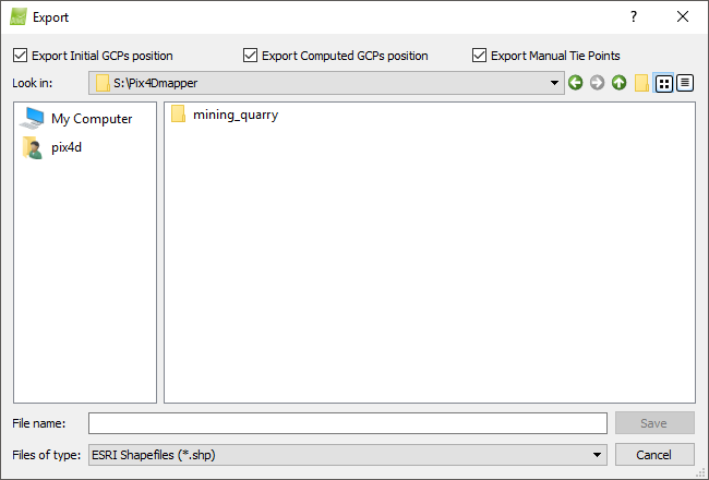
The available formats are: - AutoCad DFX (*.dfx)
- ESRI Shapefiles (*.shp)
- Keyhole Markup Language (*.kml)
- Microstation DGN (*.dgn)
On the top of the Export pop-up there are 3 check-boxes that allow the user to select what kind of points to export:
- Export Initial GCPs position: Exports the initial position of the GCPs.
- Export Computed GCPs position: Exports the computed position of the GCPs.
- Export Manual Tie Points: Export the Manual Tie Points.
By right clicking on a point layer, a context menu with the following actions appears:
- Rename: Rename the point.
- Remove: Remove the point.
This layer displays the Automatic Tie Points that are computed during initial processing. Each Tie Point is visible in at least 3 images. The Automatic layer has the following sub-element:
- Display Properties: Displays properties of the Automatic Tie Points.
- Point Size: Size for each point in the 3D View.