IN THIS ARTICLE
Layers
2D/3D view
2D/3D tools
Visualization settings and commands
Status bar
Layers details
Licenses: This article is valid for all PIX4Dcloud licenses.
Roles:
- Owners, Managers, Editors and Reader can view datasets in PIX4Dcloud.
- Only Owners, Managers, and Editors can make permanent changes (save annotations, import files, etc) in a datasets in PIX4Dcloud.
Video: The following video tutorial explains step-by-step how to visualize results in PIX4Dcloud.
Layers
On the left panel, the Layers are displayed. The available ones are the following.
 Annotations: It consists of a group of measurement objects that can be:
- Distances
- Areas
- Circles
- Volumes
- Markers
- Inspections
 GCPs: It includes GCPs and checkpoints detected and marked by the AutoGCPs functionality. For more information: GCPs layer. (Only for PIIX4Dcloud Pro licenses and above)
 Autotags: Coded Tags can be used directly in PIX4Dcatch, which are detected and marked automatically by the application. For more information, How to use Automatic Tag Detection and Manual GCP Marking - PIx4Dcatch.
.png?width=24&height=24&name=tie_points%20(1).png) Localization points: It allows for the processing of projects uploaded from PIX4Dcatch with a custom coordinate system defined by the user. For more information, How to visualize a site localization project on PIX4Dcloud.
Localization points: It allows for the processing of projects uploaded from PIX4Dcatch with a custom coordinate system defined by the user. For more information, How to visualize a site localization project on PIX4Dcloud. Design Overlays: It gathers the CAD Overlays uploaded to the site.
 Outputs: It gathers the following outputs generated during the photogrammetric processing
 Orthomosaic
 DSM
DSM Point cloud
 3D Textured Mesh
.png?width=24&height=24&name=gaussian%20(1).png) Gaussian Splat (*)
Gaussian Splat (*) Index
Index IFC
IFC
(*) Only available when processing from PIX4Dcatch
Filter by name or tag
When looking for a layer or an item of a layer in the Layers panel, the filter is a helpful tool to narrow the search.
At the top of the Layers tab,
- To filter by name: type in the layer's name or its item.
- To filter by tag: type the tag that has been previously assigned to this one to speed up the search process.
2D/3D view
The user can switch between the 2D and 3D view, using the switcher ![]() .
.
- The 2D view shows the annotations in 2D and the 2D outputs.
- The 3D view shows the annotations in 3D and the 3D outputs.
In 2D, the basemap selector allows switching between the Streets and Satellite Maps of Mapbox.
2D/3D tools
These tools allow users to select, modify, and create annotations in the 2D and 3D views. A detailed explanation is available in 2D/3D tools and annotations.
Status bar
- Coordinate system switcher: The coordinate switcher in the map viewer allows to toggle the on-screen display between the Project CRS and WGS84 for quick visualization.
- Horizontal Display (X,Y / Lat,Lon): Switching to WGS84 reformats horizontal coordinates on the fly, translating grid meters (Easting/Northing) into global decimal degrees (Latitude/Longitude).
- Vertical Elevation (Z): Elevation values remain unchanged. the Z-value stays permanently fixed to the native orthometric vertical datum baked into the model during initial processing.
- Units switcher: The unit switcher allows to display in different metric system as Metric, Imperial or US Imperial.
-
Dataset Status and Permissions Indicator:
The status bar provides real-time information regarding dataset access permissions and annotation synchronization:
- Access Permissions: Indicates the specific privileges granted by the share link used to access the dataset. It specifies whether the session has Read-only restrictions (where permanent changes are unauthorized).
- Annotation Synchronization: Displays the current saving state of project annotations (Saving, All changes saved, or Error), indicating whether recent modifications have been successfully saved to the cloud or are currently in the process of being synchronized.

Visualization settings and commands
 North indicator: Indicates the position of the North when outputs are rotated in the 2D/3D view.
 Viewer settings
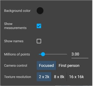
- In 2D and 3D, it allows to define:
- The visualization of the labels (measurements and names) on the annotations.
- Only in 3D, it allows to define:
- Camera control: Focused or First person modes available.
- In 2D and 3D, it allows to define:
-
-
- The color of the background.
- The number of millions of points to be displayed in the model.
- 3D Ambient occlusion: Improve the visualization of some of the 3D layers as DXF, IFC, and point cloud.
-
-
-
- Texture resolution: Three types of textures mesh can be selected. 2k x 2k, 8k x 8k (default), 16k x 16k.
Information:
- When processing directly on PIX4Dcloud, the 3D mesh resolution is always 16k x 16k.
- When processing directly on PIX4Dcloud, the 3D mesh resolution is always 16k x 16k.
- Texture resolution: Three types of textures mesh can be selected. 2k x 2k, 8k x 8k (default), 16k x 16k.
-
 Save view as default view:
- In 2D:
- It allows one to define a default 2D view that will persist every time the 2D view of the project is opened by the owner or shared with stakeholders.
- In 3D:
- It allows one to define a default 3D view that will persist every time the 3D view of the project is opened by the owner or shared with stakeholders
- In 2D:
 Take a screenshot: The command takes a JPG screenshot from the active view at the current zoom level and without the user interface.
- In 2D, the screenshot contains:
- The selected 2D layers with the selected basemap,
- The active annotations with their labels, if displayed.
- In 3D, the screenshot contains:
- The selected 3D layers with the selected background color,
- The active annotations with their labels, if shown.
- In 2D, the screenshot contains:
 Snap mode: Snap annotations to edges of design overlay files in 3D editor.
 Show my current position: (only available in 2D) It shows the user's current position. A pop-up message from the web browser will ask for permission to track the user's location if not allowed yet.
 Center Map: It allows centering the map/model onto a central point of view.
 Zoom In: It allows to zoom into the map/model.
 Zoom Out: It allows to zoom out of the map/model.
Layers details
The user can specify details and settings for the different output and annotation layers and their items.
It is also possible to select or unselect several annotations or DXF/IFC files by clicking once over the first annotation and dragging the cursor over the rest of the items under the Layer menu.
Creating folders under the Annotations layers helps to organize better and easier all the information.
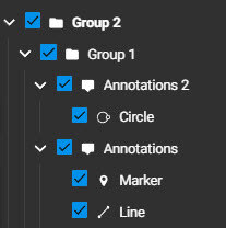
Annotations, Line, Polygon, Circle, Volume, Marker, Inspection
A detailed description of these layers can be found at 2D/3D tools and annotations.
Design Overlay files (Image and Vector design)
When clicking the DXF layer, the details panel opens on the right.
- Name
- (optional) Description
- (optional) Tags
- Settings
- Visible: set the layer as visible or not visible.
- Opacity: adjust the opacity level from 0 to 100.
- On-screen 3D custom elevation
- Set elevation: Enable reading the height value from the DXF metadata. By entering a value, the DXF is shifted to that elevation.
- Elevation: enter a custom height value manually.
GCPs: (Only for PIIX4Dcloud Pro licenses and above)
When clicking the GCP name in the layer, the details panel opens on the right.
- Name
- Type
- Coordinates
Autotags
When clicking the Autotag point name in the layer, the details panel opens on the right.
- Name
- Settings
- Visible: set the layer as visible or not visible.
- Opacity: adjust the opacity level from 0 to 100.
- Coordinates
Localization points
When clicking the point name in the layer, the details panel opens on the right.
- Type: Point name
- Local coordinates: Refers to point measure in the custom coordinate system defined by the user.
- Global coordinate: Coordinates of the point of the selected global coordinate system in PIX4Dcatch + rover.
- Residuals: Residuals of the transformation from a global to a custom coordinate system at that point.
Orthomosaic
When clicking the Orthomosaic layer, the details panel opens on the right.
- Name
- (optional) Description
- (optional) Tags
- Settings
- Visible: set the layer as visible or not visible.
- Opacity: adjust the opacity level from 0 to 100.
DSM
When clicking the DSM layer, the details panel opens on the right.
- Name
- (optional) Description
- (optional) Tags
- Settings
- Visible: set the layer as visible or not visible.
- Opacity: adjust the opacity level from 0 to 100.
- Elevation: define the elevation interval of the points to be displayed in the layer.
Point Cloud
When clicking the Point Cloud layer, the details panel opens on the right.
- Name
- (optional) Description
- (optional) Tags
- Settings
- Visible: set the layer as visible or not visible.
- Elevation: enable this option to color the Point Cloud points with a color scale reflecting the elevation gradient.
- Point size mode: options are adaptive and fixed. More information in: How to optimally visualize the Point Cloud in 3D.
- Point size: magnify the size of the points from a factor of 0.05 to 10.
3D Textured Mesh
When clicking the 3D Textured Mesh layer, the details panel opens on the right.
- (optional) Name
- (optional) Description
- (optional) Tags
- Settings
- Visible: set the layer as visible or not visible.
- Opacity: adjust the opacity level from 0 to 100.
- Back-face culling: It determines whether a polygon is displayed during the visualization. For more information, back-face culling. For more information, HERE.
Gaussian Splat
When clicking the Gaussian Splat layer, the details panel opens on the right.
- (optional) Name
- (optional) Description
- (optional) Tags
- Settings
- Visible: set the layer as visible or not visible.
- Realistic reflections: enable this option to visulize the bright spots of light (like the sun reflecting off a car hood)
Index
When clicking the Index layer, the details panel opens on the right.
- Name
- (optional) Description
- (optional) Tags
- Settings
- Visible: set the layer as visible or not visible.
- Field: Index distribution values of created Field boundaries are displayed in this section.
- Histogram: The x-axis shows the range of the pixel values in the selected layer. The y-axis shows the frequency of pixels with a specific value.
IFC
When clicking the IFC model layer, the details panel opens on the right.
- Name
- (optional) Description
- (optional) Tags
- Settings
- Visible: set the layer as visible or not visible.
- Opacity: adjust the opacity level from 0 to 100.
The Focus on ![]() is available for DXF, annotations, point cloud, 3D mesh, and IFC files when the cursor is positioned on the layer name in the left panel. It allows centering the viewer in the object.
is available for DXF, annotations, point cloud, 3D mesh, and IFC files when the cursor is positioned on the layer name in the left panel. It allows centering the viewer in the object.