A layer is a group of objects that can be displayed on the 3D View. The Layers section of the left sidebar contains the following layers:
- Objects: Contains all the volumes drawn in the Volumes view.
- Densified Point Cloud: Contains the densified point cloud generated during step 2.
- External Point Clouds: Contains the external point clouds loaded.
- Point Groups: Contains the different groups of points (each point of the densified point cloud is assigned to one group).
- Triangle Meshes: Contains Triangle Meshes (generated in PIX4Dmapper or imported).
- Processing Area: Contains the Processing Area.

Characteristics:
- By clicking on the left arrow of a layer, the sub-layers and layer properties are shown or hidden.
- By clicking on the a layer's check box, the corresponding layer is shown or hidden in the 3D View.
- The different layer properties can be edited.
- Some layers have a context menu that can be accessed by right clicking on the corresponding layer.
Objects
The Objects layer contains the Volumes sublayer, which contains the list of volumes added to the project.
The volumes layer has the following structure:
Contains the list of volumes added to the project. It can be used for volume calculation. It is defined by a 3D surface called a base. The volume is computed between the base and the terrain surface.
The Volumes layer has the following structure:
- Display Properties: This layer allows the user to edit the display properties for all the volumes.
- Vertex Color: Color of the spheres that represent the vertices of the bases of the volumes.
- Vertex Radius: Radius of the spheres that represent the vertices of the bases of the volumes.
- Line Color: Color of the lines between the vertices of the bases of the volumes.
- Line Width: Width of the lines defining the bases of the volumes.
- Base: View/hide the basex of the volumes.
- Color: Color of the bases of the volumes.
- Shader: Specifies the way each triangle of the bases of the volumes is colored. The color is related to the 3D position of each triangle. There are 2 ways of coloring the triangles available:
- Monochrome: Selected by default. The triangles are colored with a color-to-black scale depending on the angle with respect to a virtual sun positioned in the north-east at 45 degrees from the horizon. It uses the color selected above.
- Color: The triangles are colored with an RGB scale. The color of a triangle depends on the angle with respect to 3 virtual suns with Red, Green, and Blue illumination. The color of each triangle is the combination of the light received by the 3 virtual suns. This shader gives a slope map if the model is looked at from top. It gives information about the orientation of each surface.
- Terrain: View/hide the triangles defining the terrain. These triangles are generated using the base of the volume and the points above and below that surface.
- Color: Color of the triangles defining the terrain. These triangles are generated using the base surface and the points above and below that surface (this property only affects Volume objects).
- Shader: Specifies the way each triangle defining the terrain is colored. The color is related to the 3D position of each triangle. 2 ways of coloring the triangles are available:
- Monochrome: Selected by default. The triangles are colored with a color-to-black scale depending on the angle with respect to a virtual sun positioned in the north-east at 45 degrees from the horizon. It uses the color selected above.
- Color: The triangles are colored with a RGB scale. The color of a triangle depends on the angle with respect to 3 virtual suns with Red, Green, and Blue illumination. The color of each triangle is the combination of the light received by the 3 virtual suns. This shader gives a slope map if the model is looked at from top. It gives information about the orientation of each surface.
- List of Volumes: Each object has the following sub-element:
- Display Properties: This layer allows the user to edit the Display Properties of a Volume. The properties that can be edited are the same as the Display Properties of the Volumes listed above.
By right clicking on the Volumes sub-layer, a context menu with the following options appears:
- New Volume: Allows the user to draw a new volume. For step by step instructions: How to draw a Volume.
- Import Volume: Opens the Import Volume pop-up that allows the user to import Volumes created previously with PIX4Dmapper for the same area of study or created manually.
- To import a volume created previously with PIX4Dmapper, it has to be a .shp file that contains surfaces (name_surfaces.shp) or vertices (name_vertices.shp).
- To import a volume created with an external software, it has to be a .shp file that contains a 3D polygon (surface) or 3D vertices.
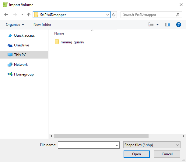
Contains the sections:
- Navigation window: Used to search for and select the file to be imported.
- File name: Displays the name of the selected file to be imported.
- Files of type: Displays the possible formats accepted for the input file: Shape files (.shp) are accepted.
And the action buttons:
- Open: Imports the selected file.
- Cancel: Does not import the Volume and exits the pop-up.
- Help: Opens the PIX4Dmapper help.
- Export All Volumes: Opens the Export pop-up that allows the user to export the corresponding components from the volume into a file.
The following file formats can be selected for export:Important: A Volume is composed of volume meshes, lines, and vertices to which Manual Tie Points are associated. - AutoCad DFX (.dfx).
- ESRI Shapefiles (.shp).
- Keyhole Markup Language (.kml).
- Microstation DGN (.dgn).
The type of components to export can be selected. The following components can be exported:
- Export Vertices: Exports the vertices of the Volumes.
- Export Surfaces: Exports the surface meshes of the Volumes.
- Export Meshes: Exports the volume meshes of the Volumes.