PIX4Dmapper inputs are:
- Images: PIX4mapper is based on image processing.
- Image geolocation file (optional): The file that contains the geolocation of the images.
- Ground Control Points (GCP) file (optional): The file that contains the coordinates of the GCPs.
- Coordinate system file (optional): The file that contains information about the coordinate system of the GCPs or the image geolocation.
- GCP/Manual Tie Points marks file (optional): The file that contains the image coordinates of the GCPs and Manual Tie Points marked on the images.
- Point cloud (optional): An external point cloud taken by other sources such as LiDAR can be imported into PIX4Dmapper to generate the DSM and Orthomosaic.
- Processing Area (optional): An area that can be imported and which defines the area for which the outputs will be generated.
- Radiometric calibration image (optional): An image that shows the radiometric calibration target
- Volume measurement vertices/area (optional): Some vertices or a surface (area) that can be imported and which define the area for which the volume measurement will be performed.
- Regions in the Index Calculator (optional): Specific regions for which the Index Maps, the Index values and the Colored Index Maps will be generated.
- Video file (optional): A video file can be imported and used for processing (instead of still images).
Images
PIX4Dmapper is an image processing software. The images can be either JPEG or TIFF files.
Multi-band TIFF (RGB / Infrared / thermal)
1 layer (no pyramid, no multi-page)
8, 10, 12, 14, 16 bit integer, floating point
Image geolocation file (optional)
PIX4Dmapper can process images with or without geolocation.
If the image EXIF data contains the image position, then the geolocation file is not needed as PIX4Dmapper automatically reads the geolocation from the EXIF data. If the EXIF data does not contain the image GPS position, then a geolocation file is needed. The geolocation file delivered by any camera or GPS system can be edited in order to be compatible with PIX4Dmapper. PIX4Dmapper can also read the geolocation files delivered by the UAVs of 3D Robotics, CropCam and QuestUAV and the cameras of Tetracam.
The files that can be imported in PIX4Dmapper are:
- Latitude, Longitude, Altitude
- Longitude, Latitude, Altitude
- X, Y, Z
- Y, X, Z
- 3D Robotics Flight Log
- CropCam Flight Log
- QuestUAV Flight Log
- Tetracam Flight Log
Latitude, Longitude, Altitude
For geographic WGS84 (latitude, longitude, altitude) image geolocation coordinates. The file is a .csv, .txt, or .dat extension file. It contains four columns per line, and uses a comma to separate the characters.
The format of the file is described in the table below:
IMG_3165.JPG,46.2345612,6.5611445,539.931234
IMG_3166.JPG,46.2323423,6.5623423,529.823423
The latitude value is between -90° and 90°.
The longitude value is between -180° and 180°
IMG_3165.JPG,46.2345612,6.5611445,539.931234,1.698,4.392,90.859
IMG_3166.JPG,46.2323423,6.5623423,529.823423,4.571,2.977,94.714
The latitude value is between -90° and 90°.
The longitude value is between -180° and 180°
IMG_3165.JPG,46.2345612,6.5611445,539.931234,1.698,4.392,90.859,5,10
IMG_3166.JPG,46.2323423,6.5623423,529.823423,4.571,2.977,94.714,5,10
The latitude value is between -90° and 90°.
The longitude value is between -180° and 180°
Longitude, Latitude, Altitude
For geographic WGS84 (longitude, latitude, altitude) image geolocation coordinates. The file is a .csv, .txt, or .dat extension file. It contains four columns per line, and uses a comma to separate the characters.
The format of the file is described in the table below:
IMG_3165.JPG,46.2345612,6.5611445,539.931234
IMG_3166.JPG,46.2323423,6.5623423,529.823423
The latitude value is between -90° and 90°.
The longitude value is between -180° and 180°
IMG_3165.JPG,46.2345612,6.5611445,539.931234,1.698,4.392,90.859
IMG_3166.JPG,46.2323423,6.5623423,529.823423,4.571,2.977,94.714
The latitude value is between -90° and 90°.
The longitude value is between -180° and 180°
IMG_3165.JPG,46.2345612,6.5611445,539.931234,1.698,4.392,90.859,5,10
IMG_3166.JPG,46.2323423,6.5623423,529.823423,4.571,2.977,94.714,5,10
The latitude value is between -90° and 90°.
The longitude value is between -180° and 180°
X, Y, Z
For image geolocation coordinates that are given in any projected coordinate system (X,Y,Z). The file is a .csv, .txt, or .dat extension file. It contains four columns per line, and uses a comma to separate the characters.
The format of the file is described in the table below:
imagename,X/Easting [meter],Y/Northing [meter],Z [meter] if the units of the system is meters
imagename,X/Easting [feet],Y/Northing [feet],z[feet] if the units of the system is feet
imagename, X/Easting [meter],Y/Northing [meter],Z [meter], omega [degrees], phi [degrees], kappa [degrees] if the units of the system is meters
imagename, X/Easting [feet],Y/Northing [feet],Z [feet], omega [degrees], phi [degrees], kappa [degrees] if the units of the system is feet
imagename, X/Easting [meter],Y/Northing [meter],Z [meter], omega [degrees], phi [degrees], kappa [degrees],Accuracy Horz [meter],Accuracy Vert [meter] if the units of the system is meters
imagename, X/Easting [feet],Y/Northing [feet],Z [feet], omega [degrees], phi [degrees], kappa [degrees],Accuracy Horz [feet],Accuracy Vert [feet] if the units of the system is feet
Y, X, Z
For image geolocation coordinates that are given in any projected coordinate system (Y,X,Z). The file is a .csv, .txt, or .dat extension file. It contains four columns per line, and use a comma to separate the characters.
The format of the file is described in the table below:
imagename,Y/Northing [meter],X/Easting [meter],Z [meter] if the units of the system are meters
imagename,Y/Northing [feet],X/Easting [feet],z [feet] if the units of the system are feet
imagename, Y/Northing [meter],X/Easting [meter],Z [meter],omega [degrees],phi [degrees], kappa [degrees] if the units of the system is meters
imagename,Y/Northing [feet],X/Easting [feet],Z [feet],omega [degrees],phi [degrees], kappa [degrees] if the units of the system is feet
imagename,Y/Northing [meter],X/Easting [meter],Z [meter],omega [degrees],phi [degrees], kappa [degrees],Accuracy Horz [meter],Accuracy Vert [meter] if the units of the system is meters
imagename, Y/Northing [feet],X/Easting [feet],Z [feet],omega [degrees],phi [degrees],kappa [degrees],Accuracy Horz [feet],Accuracy Vert [feet] if the units of the system is feet
3D Robotics Flight Log
The GPS files that 3D Robotics UAVs deliver are compatible with PIX4Dmapper and do not need any editing.
CropCam Flight Log
The CropCam Flight Log file is the GPS log file that CropCam UAVs deliver. It is compatible with PIX4Dmapper and it does not need any editing.
The format is an ASCII .txt file. It uses white space to separate the characters.
The camera is usually mounted on Servo8.
The Camera Trigger Value corresponds to the value that the camera servo takes when an image is triggered.
The first image date corresponds to the date and time the first image is taken. The first image geolocation date corresponds to the date and time of the first image geolocation. These 2 values are used to compute the offset in milliseconds between the first image and first image geolocation, in order to correctly match a geotag with each image.
QuestUAV Flight Log
The files that QuestUAV delivers are compatible with PIX4Dmapper and does not need any editing.
Tetracam Flight Log
The file exported by Tetracam's software PixelWrench2 is compatible with PIX4Dmapper and does not need any editing.
Ground Control Points (GCP) file (optional)
The GCPs are points of the area to map with known coordinates.
The GCP file format is a .csv or .txt file (ASCII). It contains four or six columns per line for 3D GCPs and 3 or 5 columns per line for 2D GCPs, and use a comma to separate the characters. The formats are described in the table below:
label,latitude[decimal degrees],longitude[decimal degrees]
GCP0,46.23456,6.56114
GCP1,46.23234,6.56234
The latitude value is between -90° and 90°.
The longitude value is between -180° and 180°
label,latitude[decimal degrees],longitude[decimal degrees],Accuracy X [meter],Accuracy Y [meter]
GCP0,46.23456,6.56114,5,10
GCP1,46.23234,6.56234,5,10
The latitude value is between -90° and 90°.
The longitude value is between -180° and 180°
label,X/Easting [feet],Y/Northing [feet] if the units of the system are in feet
label,X/Easting [meter],Y/Northing [meter],Accuracy X [meter],Accuracy Y [meter] if the units of the system are in meters
label,X/Easting [feet],Y/Northing [feet],Accuracy X [feet],Accuracy Y [feet] if the units of the system are in feet
label,latitude[decimal degrees],longitude[decimal degrees],altitude[meter]
GCP0,46.23456,6.56114,299.931
GCP1,46.23234,6.56234,299.823
The latitude value is between -90° and 90°.
The longitude value is between -180° and 180°.
label,latitude[decimal degrees],longitude[decimal degrees],altitude[meter],Accuracy Horz [meter],Accuracy Vert [meter]
GCP0,46.23456,6.56114,299.931,5,10
GCP1,46.23234,6.56234,299.823,5,10
The latitude value is between -90° and 90°.
The longitude value is between -180° and 180°.
label,X/Easting [feet],Y/Northing [feet], z[feet] if the units of the system are in feet
label,X/Easting [meter],Y/Northing [meter],z[meter],Accuracy Horz [meter],Accuracy Vert [meter] if the units of the system are in meters
label,X/Easting [feet],Y/Northing [feet], z[feet],Accuracy Horz [feet],Accuracy Vert [feet] if the units of the system are in feet
Coordinate system file (optional)
The coordinate system file is a .prj file that contains information about a particular coordinate system. It is optional.
The information contained in the .prj file specifies the:
- Name of Geographic coordinate system or Map projection
- Datum
- Spheroid
- Prime meridian
- Units used
- Parameters necessary to define the map projection, for example:
- Latitude of origin
- Scale factor
- Central meridian
- False northing
- False easting
- Standard parallels
For more information about how to obtain or create a .prj coordinate system syntax file: How to obtain or create a .prj coordinate system syntax file.
GEOGCS["GCS_North_American_1927",DATUM["D_North_American_1927",SPHEROID["Clarke_1866",
6378206.4,294.9786982],PRIMEM["Greenwich",0],UNIT["Degree",0.0174532925199433]]]
GCP / Manual Tie Point marks file (optional)
The GCPs/Manual Tie Points need to be marked on the images. Once marked, their image coordinates can be saved into a .txt, .csv or xml file (GCP/ Manual Tie Point marks file). This allows the user to use the same GCPs/Manual Tie Point marks next time needed to run the same project (e.g. adding new images to an existing project) without having to manually re-mark the GCPs/Manual Tie Points.
The GCP/Manual Tie Point image coordinate file can be a
The coordinate system has as origin the upper left part of the image. Its axes are oriented as shown in the image below:

The GCP image coordinates are given in pixels:
imagename, GCP/Manual Tie Pointlabel, image coordinate x, image coordinate y, (optional) zoom level, (optional) image directory
Each image is described in a block starting with the image name and ending with -99. The line containing the image name has 2 elements separated by a white space:
image_name other_string
The other lines in the image block describe the GCP/Manual Tie Point position of the image. The line has 3 elements separated by a white space.
GCP/Manual Tie Point_name GCP/Manual Tie Point_positionX GCP/Manual Tie Point_positionY
The GCP/Manual Tie Point_name has to be the name of a GCP/Manual Tie Point that has already been imported/created in the project.
GCP/Manual Tie Point_positionX and GCP/Manual Tie Point_positionY are the GCP/Manual Tie Point coordinates on the image.
The coordinate system has as origin the center (Cx, Cy) of the image (not the principal point). Its axes are oriented as shown in the image below:

The GCP image coordinates can be given in millimeters or in pixels.
The coordinate system has as origin the upper left part of the image. Its axes are oriented as shown in the image below:
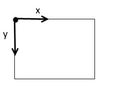
The GCP image coordinates are given in pixels.
Point Cloud (optional)
A Point Cloud generated by an external source such as LiDAR technology can be used in PIX4Dmapper to generate the DSM and Orthomosaic. If such a Point Cloud is used, the Point Cloud generated by PIX4Dmapper is not taken into account for the DSM and Orthomosaic generation.
Processing Area (optional)
If there is no need to generate the outputs for the entire area covered by the images, it is possible to import a file that defines the Processing Area. For more information about the Processing Area: Menu View > rayCloud > Left sidebar > Layers > Processing Area.
The file can have any coordinate system of the PIX4Dmapper database.
Radiometric calibration image (optional)
If there is need to calibrate and correct the image reflectance, taking the illumination and sensor influence into consideration, an image in which a reflectance target with known albedo values is shown can be imported. For more information: Menu Process > Processing Options... > 3. DSM, Orthomosaic and Index > Index Calculator.
Volume measurements vertices / area
If there is need to define the volume of a specific area, it is possible to import a .shp file with this area or the vertices that define this area. This .shp file can be generated by PIX4Dmapper or by another software (GIS, CAD). For more information about how to export a volume .shp file with PIX4Dmapper: How to export Volumes.
Regions for the Index Calculator
If there is need to define specific areas for which the Index Maps, the Index values and the Colored Index Maps will be generated, it is possible to import a .shp with the regions.
Video File
PIX4Dmapper can process video frames.
- It is not recommended to record videos for accurate mapping: The quality of the results will almost always be inferior to the results generated using still imagery.
- 4K videos from cameras such as GoPro 4 and DJI provide reasonable results.
- Full HD videos are usually not sufficient to get reasonable results.
For more information about how to use videos for processing: How to use Videos for Processing.