PIX4Dsurvey を使用すると、 断面を示す特定の断面に沿ったセクション内の点群とベクトルを視覚化できます 。 さらに、断面の内容は、断面ボックスの内容として定義されます。 このボックスのパラメータを変更したり、ボックスを水平方向やポリラインに沿って定義されたステップで移動させることができます。断面表示は、PIX4Dsurvey 1.35.0から利用可能です。
アクセス方法:
ステータスセンターで
 断面表示を選択してください。
- ステータスセンターが表示されていない場合は、メニューバーで[ビュー ]>[ コントロールパネル ]>[ ステータスセンター]を選択すると、ステータスセンターを起動することができます。
- ステータス センターを展開するには、
 をクリックします。
 - ステータス センターを折りたたむには、
 をクリックします。
本記事の内容
断面 ツールに関する一般情報
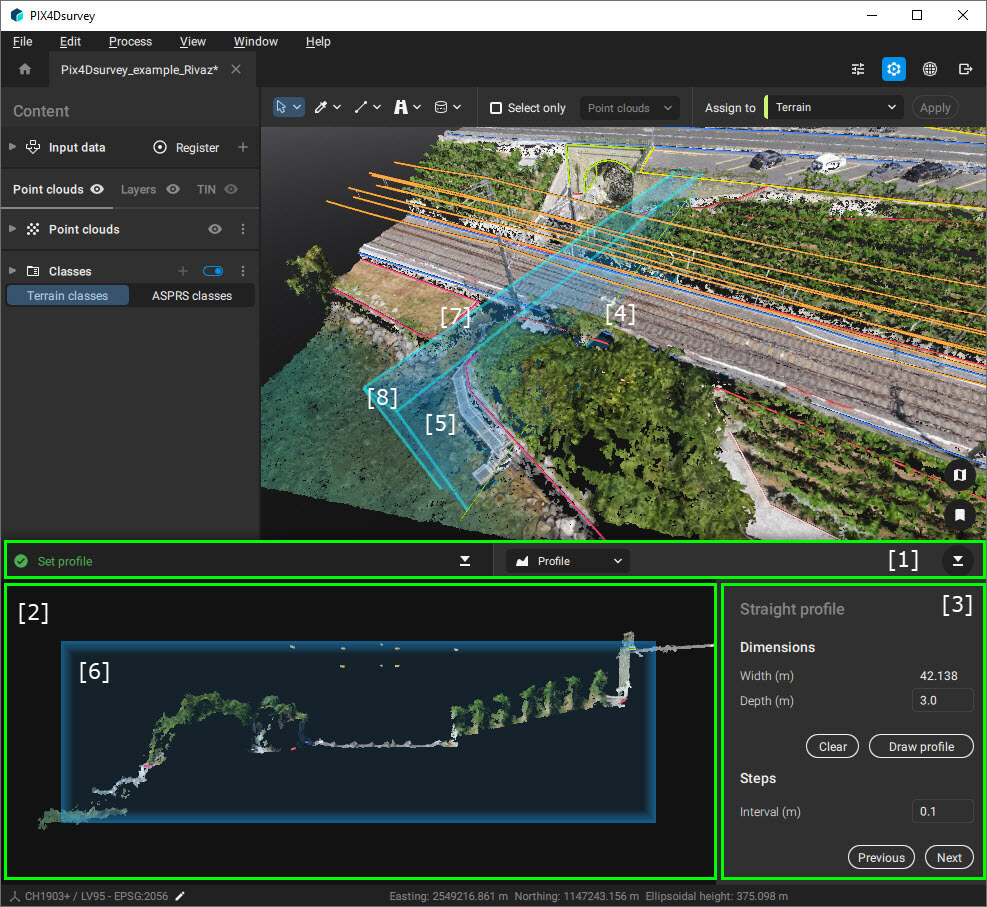
断面およびセクションツールの主な要素は次のとおりです:
- [1] ステータス バー
- [2] セクション
- [3] 断面設定
- [4] 3D ビューでの断面 (薄緑の細い線)
- [5] 断面ボックス (青いボックス)
- [6] セクションに投影された断面 ボックス
- [7] 幅
- [8] 深度
重要:断面を保存することはできません。
ヒント:
Ctrl+D キーの組み合わせを使用して、いつでも断面の描画を開始できます。
情報: マウスのスクロール ホイールを使用するか、トラックパッドのピンチ ズームを使用して、セクションを拡大します。
セクション内でパンするには、マウス カーソルでクリック アンド ドラッグします。 表示をリセットするには、 表示をリセットするボタン をクリックします。 これにより、断面ボックスに焦点を合わせた断面図がリセットされます。
セクション内でパンするには、マウス カーソルでクリック アンド ドラッグします。 表示をリセットするには、 表示をリセットするボタン
をクリックします。 これにより、断面ボックスに焦点を合わせた断面図がリセットされます。
情報: セクションのグリッドを使用して、縮尺を推定できます。 主線と副線があります。 ライン間の距離は、右下隅に表示されます。 この値は、拡大または縮小すると自動的に更新されます。
直線的な断面
直線的な断面は、さまざまなステップ( 断面の設定で説明) が互いに平行になっています。
プロジェクトで直線的な断面を描画し、そのセクションを表示するには、次の手順に従います。
- 垂直断面の作成に適した位置が見つかるまで、3Dビューで移動します。
- 展開ボタンを利用して、ステータス センターの断面表示ボタン を展開します。
- 直線的な断面ラジオ ボタンを選択します。
- 断面を描くボタンをクリックし、3Dビューをクリックして直線プロファイル作成用の線を作成します。 1回目のクリックで断面の開始を、2回目のクリックで断面の終了を定義します。
- 展開されたステータス センターに断面が表示されます。 セクションには、断面線に沿った架空の垂直面と交差するアクティブな点群とベクトル レイヤーが表示されます。
垂直方向の断面
垂直方向の断面は、ガイドとして機能する特定のポリラインに関連付けられた断面です。 ステップ機能 ( 断面の設定で説明) を使用する場合、さまざまなセクションは互いに平行ではありませんが、選択したガイド ポリラインに従います。
プロジェクトで垂直方向のプロファイルを描画し、そのセクションを表示するには、次の手順に従います。
- 3D ビューでナビゲートし、ガイドとなるポリラインまで移動します。ステップ断面が表示されます。
- 展開ボタンを利用して、ステータス センターの断面表示ボタン を展開します。
- 垂直方向の断面ラジオ ボタンを選択します。
- ポリラインの選択ボタンをクリックし、3D ビューで目的のポリラインを選択します。
- 展開されたステータス センターに断面が表示されます。 セクションには、断面線に沿った架空の垂直面と交差するアクティブな点群とベクトル レイヤーが表示されます。
断面の設定
セクションのビジュアル設定は、ステータスセンターで 断面表示 タブを展開し、必要な値を選択することで変更することができます。
- 寸法:
- 幅[単位]:この値は、水平面に投影された断面線の長さで定義され、変更することはできません
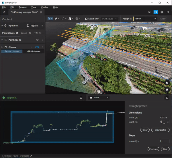
- 深度 [単位]: この値は、断面ボックスの深さを決定します。 点群からの全点と、このボックス内に存在する全ベクトルをセクションに表示します。 最小値は0.1mまたは0.1ftです。 初期値は0.3mまたは1ftです。
- ステップ
- インターバル[単位]:この値は、「前へ」または「次へ」をクリックしたときに適用されるステップ間隔の長さを定義します。 前へまたは次へボタンをクリックするたびに、断面ボックスはプロジェクト上で水平 (直線プロファイルの場合) またはポリライン (垂直プロファイルの場合) に沿って移動します。 ボックスの垂直方向のサイズは、ボックスの深さ内のプロファイルに沿ったポイントとベクトルを含むように自動的に調整されます。 最小値は0.1mまたは0.1ftです。 初期値は0.3mまたは1ftです。
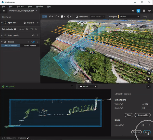
- インターバル[単位]:この値は、「前へ」または「次へ」をクリックしたときに適用されるステップ間隔の長さを定義します。 前へまたは次へボタンをクリックするたびに、断面ボックスはプロジェクト上で水平 (直線プロファイルの場合) またはポリライン (垂直プロファイルの場合) に沿って移動します。 ボックスの垂直方向のサイズは、ボックスの深さ内のプロファイルに沿ったポイントとベクトルを含むように自動的に調整されます。 最小値は0.1mまたは0.1ftです。 初期値は0.3mまたは1ftです。
ヒント: ステータス センターの断面セクションでオブジェクトを直接デジタイズし、
次へおよび
前へボタンを使用してデジタイズを続けることができます。段差部分。
ヒント: 反転ボタン
 を使用して、断面の方向を変えることができます。 これにより、
次へおよび
前へボタンの方向と断面ボックスの位置も変更されます。
を使用して、断面の方向を変えることができます。 これにより、
次へおよび
前へボタンの方向と断面ボックスの位置も変更されます。
を使用して、断面の方向を変えることができます。 これにより、
次へおよび
前へボタンの方向と断面ボックスの位置も変更されます。
ヒント:「
次へ」「
前へ」ボタンの代わりに、キーボードの「
Ctrl+Up」「
Ctrl+Down」の組み合わせを使用することも可能です。
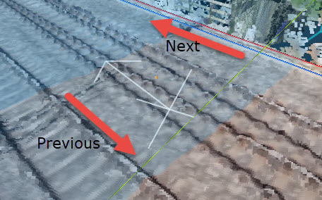
情報:
次へボタンの方向は、断面ボックスにある矢印で定義されます。
前へボタンは、薄いグレーの矢印と比較して、断面を逆方向に移動します。 断面の方向を変更するには、反転ボタン
を使用します。
を使用します。