PIX4Dsurvey allows one to vectorize point clouds made with PIX4Dmapper, PIX4Dmatic, laser scanners, LiDAR, or other third-party tools and assign the objects to layers. You can precisely define the position of the geometry by using original images or the vertex editor.

IN THIS ARTICLE
Selection tools in PIX4Dsurvey
Vectorization tools in PIX4Dsurvey
Export vector layers
Measuring vectors
How to use selection and vectorization tools in PIX4Dsurvey
Drape polyline
Editing geometry in the 3D view
Move the vertex in the 3D view
Add a vertex to existing geometry
Remove a vertex from existing geometry
Split the polyline
Join polylines
Editing geometry on images
Editing geometry with vertex editor
Editing geometry with vertex alignment
Editing geometry with polyline simplification
Selection tools in PIX4Dsurvey
The following selection tools are available in PIX4Dsurvey:
 Simple selection (default)
 Rectangular selection
 Polygon selection
 Color selection
 Road selection
Vectorization tools in PIX4Dsurvey
The following vectorization tools are available in PIX4Dsurvey:
 Polyline
 Marker
 Polygon
 Circle
 Arc
Arc Catenarys
 Assisted road marking
 Assisted curb detection (Beta)
How to use selection and vectorization tools in PIX4Dsurvey
Selection tools specifics:
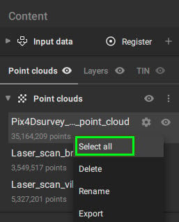
- Simple selection (default): Click on the object to select it. Right-click on the object to use Delete, Move to vector layer, Move to volume layer, Convert to, Invert selection, or Zoom to selection.
Note: Move to vector layer and Move to volume layer allow only to move an object to a non-locked layer.
- Rectangular selection: Hold Ctrl or ⌘ to freeze the screen and select the points in the point cloud, points in the Grid of Points, vector layers, or all objects in the selected area.
- Polygon selection: Select the points in the point cloud, points in the Grid of Points, vector layers, or all objects in the selected area.
- Color selection: Select points based on color, tolerance, and radius.
- Road selection: Select points based on color, tolerance, elevation, and spatial continuity.
Vectorization tools specifics:
- Polyline: Minimum of two points need to be clicked in the 3D view to define a polyline.
- Marker: Click on a point in the 3D view to create a marker.
- Polygon: Minimum of three points need to be clicked in the 3D view to define a polygon.
- Circle: To draw a circle, there are two different methods:
- Center, radius: The first vertex defines the center of the circle, and the second vertex defines a point at the circumference. Circle objects are always horizontal, and the elevation is defined by the point of the point cloud selected for the center. The second point must also be in the point cloud, but the circle will be drawn at the altitude of the center defined by the first point.
- 3 points. Select three points to adjust a circle that contains these three points.
Tip: Circle objects are always horizontal. To match the circle on the terrain: Convert the circle to a polyline (right click > convert to polyline) and then drape the polyline to the point cloud (right click > drape polyline). - Catenary: For vectorization of freely hanging power lines, chains and ropes. Minimum three points need to be clicked in the 3D view.
Tip: When vectorizing catenaries, the order of the clicks is not important. The mathematical line that represents the catenary curve will be calculated based on all clicked points. - Arc: To draw an arc are neccesary three points.
- Assisted road marking: Click on two points on the line to automatically vectorize it. For more: Assisted road marking.
- Assisted curb detection: Click on two points on the curb to automatically vectorize it. For more: Assisted curb detection.
- Roof detection: Click on every roof to automatically vectorize it. For more: Roof detection.
Circle objects can be converted into polygons or polyline (right click > convert to polygon/polyline).
To use the selection and vectorization tools:
- Select the tool on the toolbar.
- Left-click on the point cloud in the 3D view to create the first vertex and to start the vectorization.
- Continue using the left-click to add more vertices to the geometry.
- (Optional) Press the Esc key to cancel the vectorization.
- To finish the geometry:
- Right-click in the 3D view to add the last vertex and to finish the geometry.
- Alternatively, press Enter to accept the edits and to finish the geometry.
- (Optional) Right-click again to exit the vectorization tool and to change to Simple selection (default).
It is also possible to remove points from an existing selection by pressing the Alt key (Windows) or Option ⌥ key (macOS) when creating the new selection.
Drape polyline
It is possible to drape any polyline over the point cloud. This will create vertices that fit the top part of the point cloud.
To use the drape polyline tool:
- (optional) Disable the non-terrain points (the terrain filter must have run).
- Select a polyline.
- Right-click on the selected polyline to display a contextual menu.
- Choose the Drape polyline option from the contextual menu.
- The polyline will be draped over the visible point cloud, and the polyline simplification window with the Complexity slider will appear.
- (optional) The Complexity slider can be adjusted until the draped polyline fits the required specifications.
Export vector layers
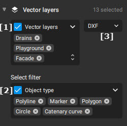
The vector layers that need to be exported can be filtered to match your requirements. It is possible to select specific layers [1] and/or filter by object type [2].
The vector layers can be exported in .dxf, .zip shp, .shp, GeoJSON, and .csv (only for makers), LandXML, HTML and PDF formats [3].
If the .csv format is selected (comma-separated values), only markers will be exported. The format of the resulting table can be selected.
| Format | Meaning |
| PENZDL | Point name, Easting coordinate, Northing coordinate, Z coordinate, Description, Label |
| PNEZDL | Point name, Northing coordinate, Easthing coordinate, Z coordinate, Description, Label |
| PXYZDL | Point name, X coordinate, Y coordinate, Z coordinate, Description, Label |
| PYXZDL | Point name, Y coordinate, X coordinate, Z coordinate, Description, Label |
| PENZD | Point name, Easting coordinate, Northing coordinate, Z coordinate, Description |
| PNEZD | Point name, Northing coordinate, Easthing coordinate, Z coordinate, Description |
| PXYZD | Point name, X coordinate, Y coordinate, Z coordinate, Description |
| PYXZD | Point name, Y coordinate, X coordinate, Z coordinate, Description |
| PENZL | Point name, Easting coordinate, Northing coordinate, Z coordinate, Label |
| PNEZL | Point name, Northing coordinate, Easthing coordinate, Z coordinate, Label |
| PXYZL | Point name, X coordinate, Y coordinate, Z coordinate, Label |
| PYXZL | Point name, Y coordinate, X coordinate, Z coordinate, Label |
| PENZ | Point name, Easting coordinate, Northing coordinate, Z coordinate |
| PNEZ | Point name, Northing coordinate, Easthing coordinate, Z coordinate |
| PXYZ | Point name, X coordinate, Y coordinate, Z coordinate |
| PYXZ | Point name, Y coordinate, X coordinate, Z coordinate |
| ENZ | Easting coordinate, Northing coordinate, Z coordinate |
| NEZ | Northing coordinate, Easthing coordinate, Z coordinate |
| XYZ | X coordinate, Y coordinate, Z coordinate |
| YXZ | Y coordinate, X coordinate, Z coordinate |
Additional information about the export tool can be found in the Export - PIX4Dsurvey page article.
Measuring vectors
Vectorized objects can be measured. This can be done following the instructions found in the How to measure points, distances, areas, or volumes - PIX4Dsurvey article.
Editing geometry in the 3D view
To move the vertex in the 3D view
- Use the Simple selection tool to select an object.
- Click on the existing geometry.
- Click on the vertex and drag it to the new position.
Tip: To speed up the editing, move to the next vertex using the Tab shortcut.
After moving the vertex to the new position, the edits are automatically taken into account and you can continue creating new geometries or edit existing ones.
To add a vertex to existing geometry
- Use the Simple selection tool to select an object.
- Hover over the section where you would like to add the vertex.
- Click to create a new vertex.
To remove a vertex from existing geometry
- Use the Simple selection tool to select an object.
- Click on the existing geometry.
- Click on the vertex and press the Delete key.
To split the polyline
- Use the Simple selection tool to select an object.
- Right-click on the vertex where you would like to split the polyline.
- Click Split polyline.
After the polyline is split, two separate polylines are created. The polylines share the vertex in which they were split.
To join polylines
- Use the Simple selection tool to select the first polyline.
- Hold Shift and select the second polyline.
- With Shift still pressed, right-click on the shared vertex and click Join polylines.
After the polylines merged, a single polyline is created.
To continue polylines
- Use the Simple selection tool to select an object.
- Select the vertex where you want to continue the polyline. The polyline can only be continued from the ends.
- Right-click on the vertex
- Click Continue polyline
Editing geometry on images
To move the vertex on the images:
- Use the Simple selection tool to click on an object.
- Click on the vertex on the image and drag it to the new position on at least two images.
- Press Enter to accept the edits.
Tip: To speed up the vectorization, accept the edits by simply clicking in the 3D view or moving to the next vertex using the Tab shortcut.
- (Optional) Hit the Esc key to cancel the edit.
After moving the vertex to the new position on at least two images, the position of the vertex is automatically changed and updated.
Editing geometry with vertex editor
It is possible to manually adjust the coordinates of created vertices.
To move the vertex using the vertex editor:
- Use the Simple selection tool to select an object.
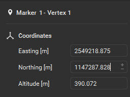
- Click on the vertex, the center will become purple. The dialog Coordinates opens in the bottom left corner of the screen.
- Edit the coordinate values by:
- Typing the new coordinate values.
- Adjust the coordinate values with the +/- button or by typing the new value.
- Click the Ctrl+Enter keys to accept the edits.
Tip: To speed up the vectorization, accept the edits by simply clicking in the 3D view.
- (Optional) Hit the Esc key to cancel the edit.
Editing geometry with vertex alignment
In the case of objects with more than 1 vertex (polylines, polygons, volume polygons), it is possible to align the vertices to a specific altitude.

To vertically align the vertices:
- Use the Simple selection tool to select an object.
- To access the vertical alignment menu, click Align Vertices
 located near the object name in the bottom left corner of the PIX4Dsurvey window and choose the desired alignment:
 Align to the highest: All the vertices of the selected object are moved vertically to align with the highest vertex.
 Align to the average: All the vertices of the selected object are moved vertically to align with the average altitude of all vertices of the selected object.
 Align to the lowest: All the vertices of the selected object are moved vertically to align with the lowest vertex.
- Custom height: All the vertices of the selected object are moved vertically to align with the given custom height.
Editing geometry with polyline simplification
It is possible to simplify a complex polyline in order to make it simpler by reducing the number of vertices. This can be particularly useful when the polyline is draped on the point cloud, as many points might be in a straight line.

To modify the polyline simplification, follow these steps:
- Use the simple selection tool to select the polyline.
- To access the polyline simplification menu, click on Polyline simplification
 located near the object name in the bottom left corner of the PIX4Dsurvey window.
 - Adjust the level of simplification using the slider, which ranges between 1 and 10
- 1: maximum level of simplification.
- 8 (default): default level of simplification.
- 10: no simplification. All vertices are kept.