This article provides step-by-step instructions on how to import and mark Manual Tie Points (MTPs) using two methods: using the rayCloud and using the GCP/MTP Manager.
An Automatic Tie Point (ATP) is a 3D point corresponding to a keypoint that is automatically detected and matched in the images.
A Manual Tie Point (MTP) is a 3D point corresponding to a keypoint that is marked (clicked) by the user in the images. A typical use is for assessing and improving the reconstruction accuracy.
There are two methods to import MTPs into PIX4Dmapper:
Using the rayCloud
The Manual Tie Points can be introduced in a project using the rayCloud, only after step 1. Initial Processing has been completed.
1. On the menu bar, click View > rayCloud.
2. In the 3D view, select a point where the MTP needs to be added.
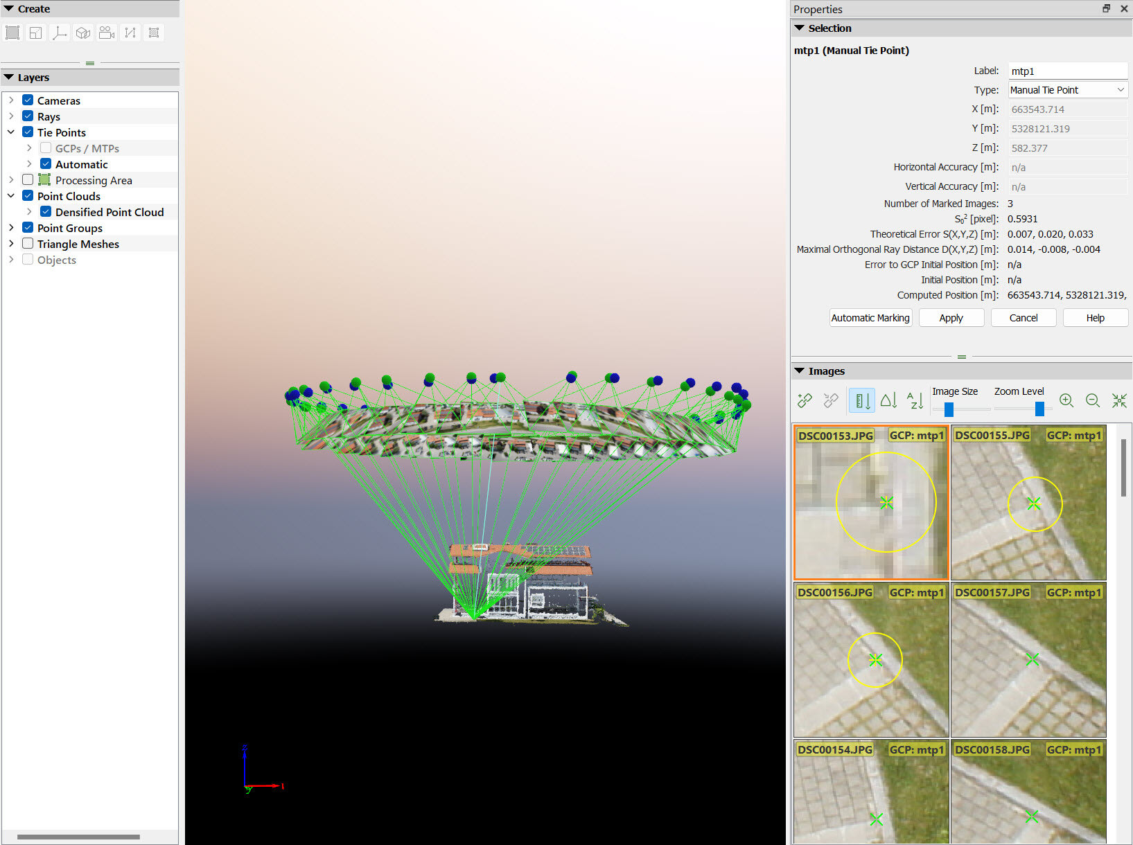
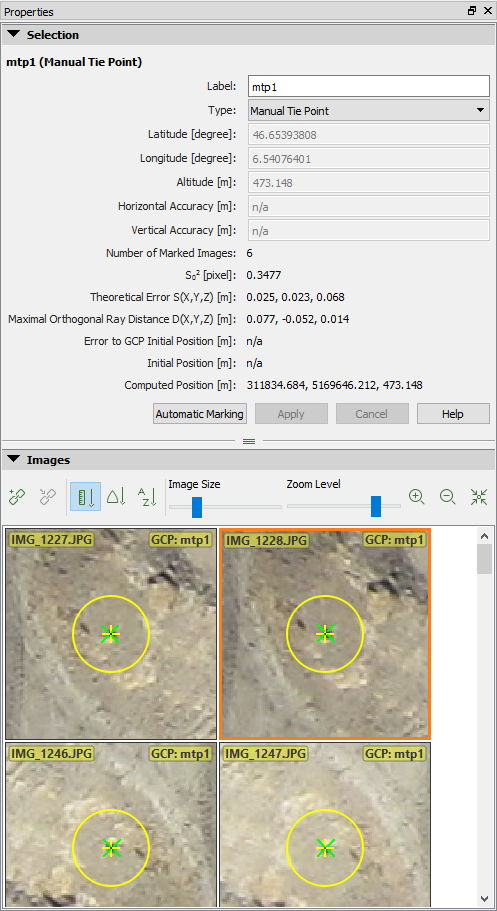
- On the right sidebar, in the Images section, all the images in which the clicked (selected) point is visible will appear.
- A green cross appears on all images, symbolizing the projected position of the selected point. Some images (at least two) also have an orange cross, which indicates the position on which this point was found to compute its 3D position.
3. Click  New Tie Point to insert a new Manual Tie Point.

4. A new MTP and its information are added on the right sidebar in the Selection section.
5. (optional) Change the name: Double-click the Label cell of the Manual Tie Point and type the desired name.
6. Navigate on each image to find the exact location of the Manual Tie Point:
- Zoom in: Moving the mouse scroll wheel forwards.
- Zoom out: Moving the mouse scroll wheel backward.
- Pan: Using the mouse left clicking.
- Change the size of the images: Move the slider of the Image Size bar.
7. Mark the Manual Tie Point on at least two images using the left mouse click.
- When marking MTPs on the images, each mark is used to compute a new 3D point. At least two images need to be marked in order to compute the estimated 3D position of the point. The estimated 3D point is reprojected on all the images in which it might be visible.
- The clicked position appears with a yellow cross and circle. The size of the yellow circle indicates the zoom level in which the marking has been done. Points that have been marked on a high zoom level are taken more into account than points that have been marked on a lower zoom level.
- After clicking on 2 images, a green cross appears on all images. The green cross represents the reprojection of the estimated 3D point on all images, and is calculated (after having marked 2 images) according to the clicks already made for the Manual Tie Point.
- After clicking on 2 images, an outlier is indicated with a pink circle when the point is erroneously marked on other images. Outliers do not influence the resulted reconstruction.
8. Check the images that have not been marked:
- If the green cross corresponds to the correct Manual Tie Point position, then there is no need to mark the point on more images.
- If the green cross does not correspond to the correct Manual Tie Point position, click on more images. Every time when the user clicks on one image, the green cross approaches more the correct place.
9. (optional) Click Automatic Marking to automatically mark the 3D point in the images that have not been marked.
10. When the green cross is at the correct place in most images, click Apply.
11. Repeat steps 2 to 10 to add more Manual Tie Points.
12. When all Manual Tie Points are marked on the images, click Process > Reoptimize. This reoptimizes the reconstruction using the Manual Tie Points.
13. (optional) To generate the new Quality Report, click Process > Generate Quality Report.
Using the GCP/MTP Manager
The Manual Tie Points can be introduced in a project using the GCP/MTP Manager before running step 1. Initial Processing.
Adding Manual Tie points in the GCP/MTP Manager:
1. On the Menu bar, click Project > GCP/MTP Manager...
2. On the GCP/MTP Manager, click Add Point under the GCP/MTP Table section.
3. (optional) Change the name: Double click the Label cell of the Manual Tie Point and type the desired name.
4. Repeat steps 1 to 3 for the other Manual Tie Points. For more information about the GCP/MTP Table properties, GCP / Manual Tie Point Table - PIX4Dmapper
Marking the added Manual Tie Point in the Basic GCP/MTP Editor:
1. On the GCP/MTP Manager, under the section GCP/MTP Editor, click Basic Editor..., the Basic GCP/MTP Editor appears:
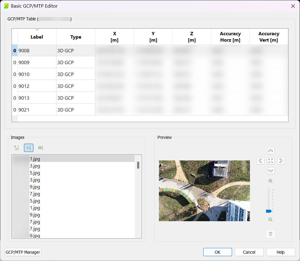
2. Click on the Manual Tie Point to be marked in the table.
3. Under the Images section, select the image in which the Manual Tie Point should be marked. After the selection, the image is displayed in the Preview section.
4. Navigate in the image by:
- Zoom in: Moving the mouse scroll wheel forwards.
- Zoom out: Moving the mouse scroll wheel backward.
- Pan: Using the mouse left-click.
- Zoom in quickly on a specific point in the image: point with the mouse the point and press the Alt key. The view returns to the last zoom level when the key is released.
- Zoom out to preview the zero zoom level: Press the Shift key. The view returns to the last zoom level when the key is released.
5. Left-click on the image to mark the point.
6. (optional) click  to remove a mark.
7. On the Images section, select the next image on which the Manual Tie Point will be marked.
8. Repeat the above steps 2-7 to mark other Manual Tie Points.
9. Click OK.