As the image acquisition plan has a high impact on the quality of the results, it is important to design it carefully.
If the Rapid/Low Res processing does not yield good results, very probably, the dataset is not adequate and it is necessary to acquire images again. In some cases, the Rapid/Low Res option fails while the Full processing successfully reconstructs the model.
For more information about the difference between Rapid/Low Res and Full processing: Full Processing vs Rapid / Low Resolution.
Ideal image acquisition plan
The ideal image acquisition plan depends on the type of terrain/object to be reconstructed.:
- General case: For projects that do not include forests, snow, lakes, agricultural fields and/or other terrains that are difficult to reconstruct.
- Forest and dense vegetation: For a project with areas covered by forest or dense vegetation.
- Flat terrain with agriculture fields: For flat terrain with homogeneous visual content such as agriculture fields.
- Building reconstruction: For 3D modeling of buildings.
- Special cases: For snow, sand, and water surfaces (oceans, lakes, rivers, etc).
- Corridor mapping: For projects with a linear area of interest (roads, rivers, etc).
- Multiple flights: For projects with images taken using multiple flights.
- City reconstruction (visible facades): For 3D modeling of urban areas.
- 3D interior reconstruction: For 3D modeling of the interior of buildings
- Mixed reconstruction: For combined datasets (interior/exterior and/or aerial/terrestrial and/or nadir/oblique).
- Large Vertical Objects reconstruction: For 3D modeling objects that are tall and slender.
- Tunnel reconstruction: For 3D modeling of a tunnel.
- Thermal: For datasets acquired with thermal cameras.
- Small objects: For 3D modeling of small objects.
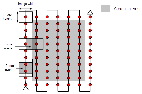
General case
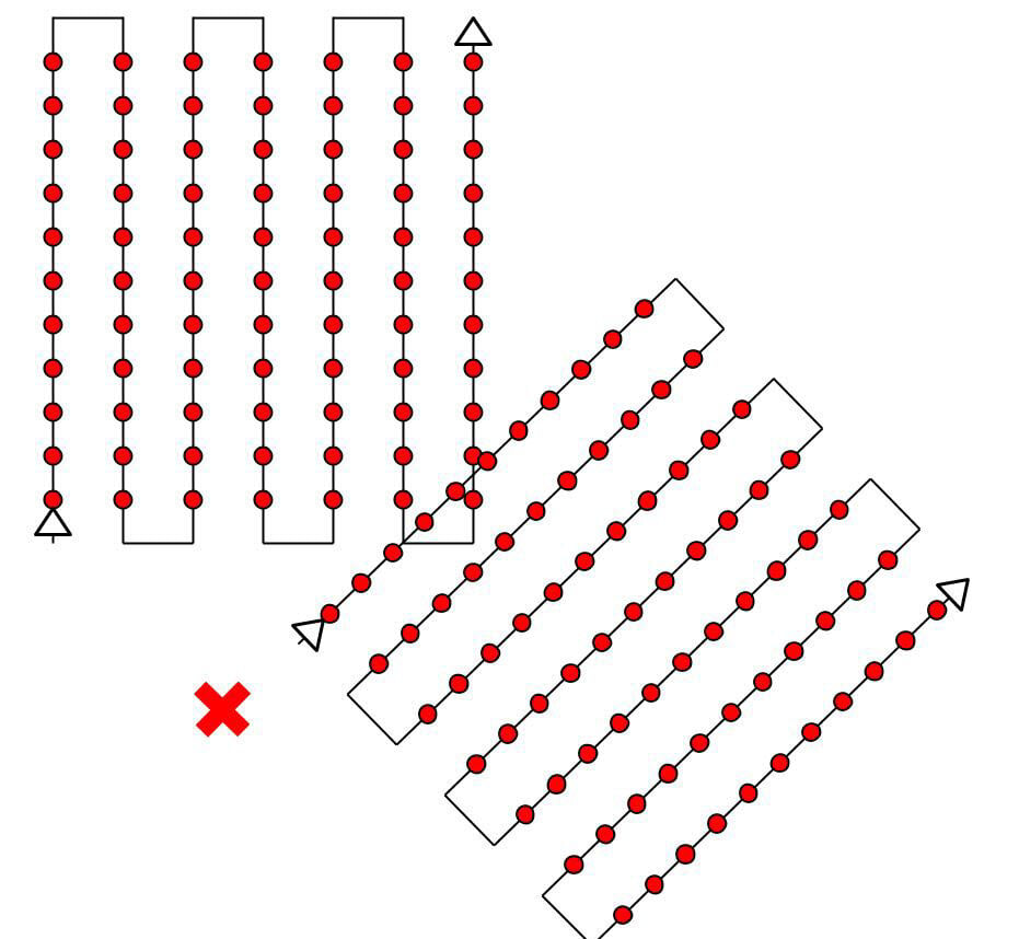
The recommended overlap for most cases is at least 75% frontal overlap (with respect to the flight direction) and at least 60% side overlap (between flying tracks). It is recommended to take the images with a regular grid pattern (Figure 1). The camera should be maintained as much possible at a constant height over the terrain/object to ensure the desired GSD.
Forest and dense vegetation
Trees and dense vegetation often have a very different appearance between overlapping images due to their complex geometry (thousands of branches and leaves). Therefore, it is difficult to extract common characteristic points (keypoints) between the images. In order to achieve good results, it is recommended to use a grid image acquisition plan like the one described in the General Case section by applying the following changes:
- Increase the overlap between images to at least 85% frontal and side overlap.
- Increase the flight height: At higher altitudes, there is less perspective distortion (therefore causing fewer appearance problems) and the dense vegetation has better visual properties. In other words, it is easier to detect visual similarities between overlapping images in such areas. The flight height in combination with the image pixel resolution and the focal length determines the Ground Sampling Distance (spatial resolution) of the images. Best results are obtained with a GSD higher than 10cm/pixel.
For more information about how to improve the results of dense vegetation areas select the correct processing options: How to improve the outputs of dense vegetation areas?
Flat terrain with agricultural fields
In cases where the terrain is flat with homogeneous visual content such as agriculture fields, it is difficult to extract common characteristic points (keypoints) between the images. In order to achieve good results, it is recommended to use a grid image acquisition plan like the one described in the General Case section by applying the following changes:
- Increase the overlap between images to at least 80% frontal and side overlap.
- Fly higher. In most cases, flying higher improves the results.
- Have accurate image geolocation and use the Agriculture template. For more information about the Agriculture (Ag) template: Processing Options Default Templates.
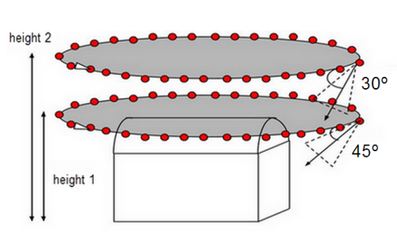
Building reconstruction
Reconstructing 3D buildings requires a specific image acquisition plan (Figure 2):
- Orient the pitch of your camera so that the majority of the image frame is filled with the object that you want to reconstruct and objects that you do not want to reconstruct comprise the minority of the image frame. There is no perfect camera pitch angle that can be applied to all missions.
- Fly a second and third time around the building increasing the flight height and decreasing the camera angle with each round.
- It is recommended to take one image every 5-10 degrees to ensure enough overlap, depending on the size of the object and its distance to it.
- The flight height should not be increased more than twice between the flights, as different heights lead to different spatial resolutions. For more information: Can PIX4Dmapper process Images taken at different Flight Heights?.
- PIX4Dmapper generates a high-quality point cloud for oblique images of buildings. However, no orthomosaic is generated, when the selected template is 3D Models: Processing Options Default Templates.
The images should have enough overlap in each dataset and between datasets. For such cases, it is strongly recommended to use GCPs or Manual Tie Points to adjust the different sets of images properly.
Special cases
This section presents some hints for terrain that is difficult to map such as terrains with snow, sand, lakes, etc.
Snow and sand have little visual content due to large uniform areas. Therefore:
- Use a high overlap: At least 85% frontal overlap and at least 70% side overlap.
- Set the exposure settings accordingly to get as much contrast as possible in each image.
Water surfaces have almost no visual content due to large uniform areas. Sun reflection on the water and waves cannot be used for visual matching.
- Oceans are impossible to reconstruct.
- To reconstruct other water surfaces such as rivers or lakes, each image needs to have land features. Flying higher may help to include more land features.
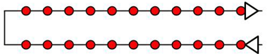
Corridor mapping
Mapping a corridor such as a railway, road, or river requires at least two flight lines (Figure 3). GCPs are not required but are recommended to improve the accuracy of the reconstruction. For more information about the number and distribution of GCPs in corridor mapping: Number and distribution of ground control points (GCPs) in corridor mapping.
For a dual track, it is recommended to use at least 85% frontal overlap and at least 60% side overlap.
It is possible to use nadir images or oblique images. For flat terrain, it is recommended to use nadir images.
If a dual-track image acquisition plan is not possible, a single-track image acquisition plan can be used if (Figure 4):
- Overlap is high enough: At least 85% frontal overlap.
- Ground control points (GCPs) are defined along the flight line in a zigzag pattern.
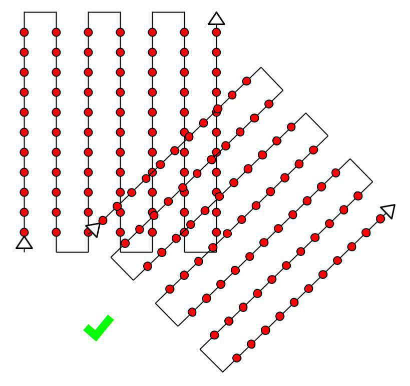
Multiple flights
PIX4Dmapper can process images taken from multiple flights. When designing the different image acquisition plans, make sure that:
- Each plan captures the images with enough overlap.
- There is enough overlap between 2 image acquisition plans (Figure 5).
- The different plans are taken as much as possible under the same conditions (sun direction, weather conditions, no new buildings, etc.).
There is a special way to process datasets taken from multiple flights, for step by step instructions: Processing Large Datasets.
City reconstruction (visible facades)
The 3D reconstruction of urban areas requires a double grid image acquisition plan so that all the facades of the buildings (north, west, south, east) are visible on the images. The overlap should be the same as in the General Case.
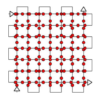
For the facades to be visible, the images should be taken with an angle between 10o and 35o (0° - the camera is looking down). If much detail is needed, aerial and terrestrial images should be combined.
The images should have enough overlap in each dataset and between datasets. For such cases, it is strongly recommended to use GCPs or Manual Tie Points to adjust the different sets of images properly.
3D Interior reconstruction
For interior reconstruction, it is strongly recommended to use terrestrial images. High overlap is needed (90%). Therefore, it is recommended to use a fisheye lens camera.
Manual Tie Points improve the reconstruction and help to properly adjust the model. For more information: webinar.
Mixed reconstruction
It is possible to combine interior/exterior and/or aerial/terrestrial and /or nadir/oblique. Any combination is possible.
The images should have enough overlap in each dataset and between datasets. For such cases, it is strongly recommended to use GCPs or Manual Tie Points to adjust the different sets of images properly. For more information: webinar.
Large Vertical Objects reconstruction
The 3D reconstruction of objects that are tall and slender requires a specific image acquisition plan (Figure 8):
- Fly close to the structure.
- Turn several times around the structure at several heights.
- Images should be taken with high overlap: 90% of overlap between images taken at the same height and 60% of overlap between images taken at different heights.
- Everything in the image frame must be in focus, including objects in the background that are outside the project area.
- Having image geolocation is recommended.
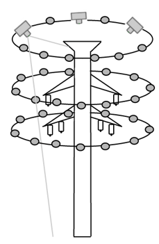
Power Tower
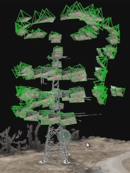
Power Tower reconstructed in the rayCloud
Tunnel reconstruction
PIX4Dmapper can reconstruct tunnels. The biggest challenge for tunnel reconstruction is the lighting conditions. If the lighting is good either with natural light (if the tunnel is not too long) or with artificial light, the reconstruction could be very good.
In case of very dark tunnels, a tripod is recommended.
- Use a fisheye lens camera.
- Take images in more than one line (avoid single-track shooting). If a multiple-track image acquisition plan is not possible, a single track could work. GCPs are highly recommended in this case.

Figure 9. Automatic Tie Points of a tunnel.
Thermal
For a better reconstruction of the captured scene in a thermal project, some recommendations should be followed during the image acquisition:
- Have very high overlap: 90% front and side image overlap.
- The images have been taken at a resolution of at least 640x480.
- The images do not suffer from motion blur. An increased flight speed may cause a blurred image.