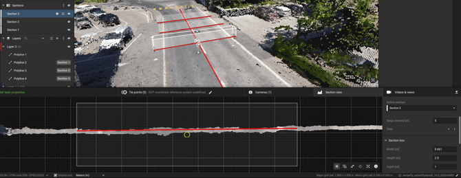
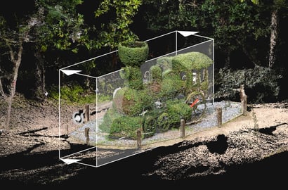
PIX4Dmaticでの断面図。
注:この 機能は、PIX4Dmatic 1.63 以降で利用可能です。
アクセス
「断面図」を表示するには:
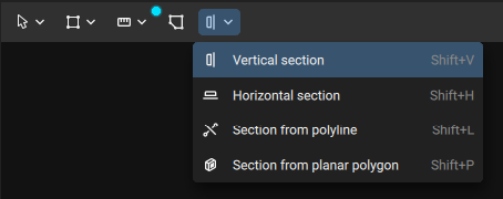
- 3Dビューのツールバーから:
- 断面図

- 横断面

- ポリラインの一部

- 平面上の多角線の断面

- 断面図
セクションの作成方法
ユースケースに応じて、(3Dビューで)3つの方法を利用できます:
- 断面図(縦断面および横断面):希望の位置を示す線を描きます。
- ポリラインからの断面:複数の断面の基準線として機能するポリラインを選択します。この方法は主に、地形や道路の作業フローで使用され、ポリライン(例:道路の中心線)を選択することで、長距離にわたって断面作成を統一します。
ヒント: 複数の並列セクションを作成するには、パネルの上部に間隔を定義し、 < > 矢印キーで各セクションを順に表示します。
- 平面上のポリゴンから断面を作成します。頂点の位置にかかわらず、ポリゴンと同じサイズと向きを持つ断面ボックスが作成されます。ポリゴンは平面上のジオメトリである必要があります。
注:ポリゴンの向きを確認するには、「面の向き」を有効にする必要があります。このオプションは、「設定」>「表示オプション」にあります。
セクションボックスの調整
セクションボックスは、下部パネル内の表示領域を定義します。半透明の面はセクション平面を表しており、ボックスの内部を向いています。この平面が、ベクトル化の対象となる領域の方を向いていることを確認してください。
セクションボックスを調整するには、2つの方法があります:
- 3Dビューから: 箱の位置を素早く大まかに調整します。
- 下部パネルから:ボックスの高さ、幅、奥行き、およびX、Y、Z軸上の回転を精密に調整できます。奥行きは下部パネルに表示される領域を決定し、この方法により回転角度をより細かく制御できます。
断面平面を調整するには:
- マウスのスクロールホイール、またはトラックパッドでのピンチ操作で、セクションを拡大表示します。
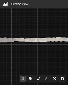
マウスカーソルをクリックしてドラッグすると、セクション内をパンできます。 - グリッドを表示または非表示にするには、[有効にする] または [無効にする] をクリックしてください。 グリッドを表示
 ボタン。このセクションのグリッドは、縮尺の目安として利用できます。目盛線と補助線が表示されています。線と線の間隔は右下隅に表示されています。この値は、ズームインまたはズームアウトすると自動的に更新されます。
 - 断面平面を点群にスナップするには、[ Snap to point cloud
 ボタン
ボタン - Invert section direction アイコン
 in the bottom panel.
 - To rotate the section between horizontal and vertical, click on the Rotate section 90°
 ボタン。
ボタン。 - To reset the view, click on the Reset view ボタン
 . This will reset the section view focusing on the profile box.
 - For more information, click on the 情報 ボタン
 .
.
Note: To determine the orientation of the section box, an orientation arrow is displayed, indicating the direction in which the box is facing.
ベクトル化
断面ボックスを作成したら、次は手動で、あるいは「ドレーピング」機能を使用して、それをベクトル化する必要があります。
「 ドレーピング」機能は 、地形に最適なポリラインを自動的に特定し、そのポリラインを断面図と3Dビューの両方に適用します。
この機能を使用するには:
- Select a section box from the 3D view
- 「ドレーピング」へ移動
- セクション内の「Drape」をクリックしてください
断面図と3Dビューにポリラインが自動的に作成されます。「Drape in section」を使用する際は、シーンにポリラインが表示されたら、その複雑さを調整してください。
各セクションは、コンテンツパネルの「セクション」の下に一覧表示され、ナビゲーション、表示/非表示の切り替え、削除、およびエクスポート対象の選択が容易に行えます。
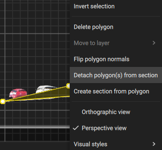
ジオメトリ(ポリラインなど)は、他の要素とともにベクトルレイヤーに保存されます。手動または「 断面への配置」機能を使用して作成されたすべてのジオメトリは、断面平面に固定されており、編集は「断面ビュー」の下部パネルでのみ可能です。ジオメトリを断面平面の外に移動することはできません。この固定を解除するには:
- コンテンツパネルからそのセクションを削除すると、ジオメトリが有効になります。
- 右クリック the geometry in the Section view panel and select Detach [geometry] from section
Tip: For sections created from a polyline (select polyline), offset the section box by the desired amount, place it in the preferred location, or fill in the information in the pop-up and confirm.
オーソプレーン
The Orthoplane feature generates orthomosaics for vertical and horizontal surfaces, such as building facades or floor plans. It provides accurate, scaled 2D representations. Orthoplane is ideal for architectural surveys, inspections, and preservation projects, offering precise measurements and detailed visual information without distortion. It integrates seamlessly with existing georeferencing and photogrammetry techniques to ensure accurate mapping of vertical structures. For more information on how to use this tool: How to create an orthoplane - PIX4Dmatic.
注: Orthoplane機能は 、PIX4Dmatic 1.66以降で利用可能です。
エクスポート
After creating the Section view and modifying the settings, click on Export to export the Section view to the location identified in the Destination setting. The status bar will be updated with the progress of the export.
After the export is complete, a .dxf file will be created in the desired location for further use. The .dxf file will contain the polyline(s) created within each Section view.