How to add / import and mark manual tie points (MTPs) in the rayCloud

Follow
 
Video: Watch the instructional video about manual tie points:

An automatic tie point (ATP) is a 3D point corresponding to a keypoint that is automatically detected and matched in the images.
A manual tie point (MTP) is a 3D point corresponding to a feature that is marked (clicked) by the user in the images. It is used for assessing and improving the reconstruction accuracy.

Manual tie points can be added using rayCloud after step 1. Initial Processing has been done.

1. On the menu bar click View > rayCloud.
2. In the 3D view, select a point in the area where the MTP has to be added.

 
Note:
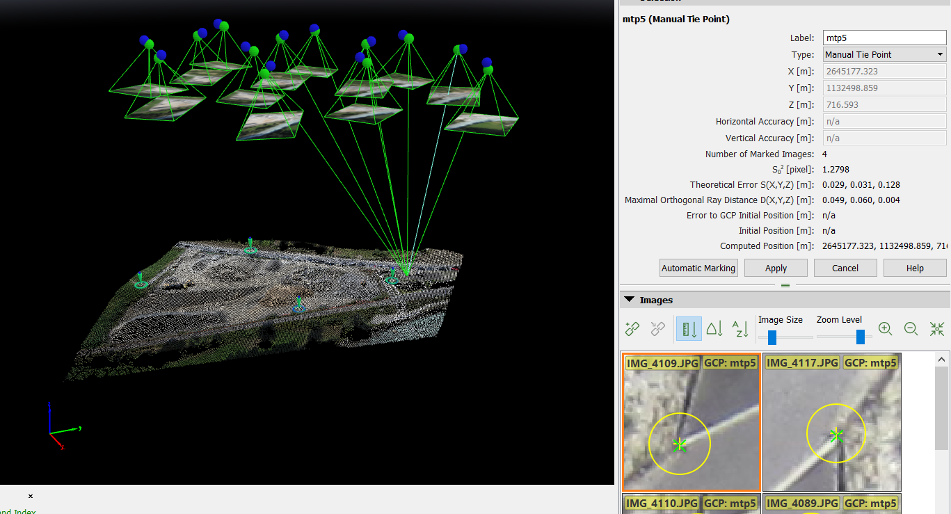
  • On the right sidebar, on the Images section, all the images, in which the clicked (selected) point is visible, appear.
  • A green cross appears on all images that symbolizes the projected position of the selected point. Some images (at least two) have also an orange cross, which indicates the position on which this point was found in order to compute its 3D position.

MTP.png

3. Click tie_point_add.pngNew Tie Point to insert a new manual tie point.

NewTiePoint.png

4. A new MTP and its information are added on the right sidebar, in the Selection section.
5. (optional) Change the name: Double-click the Label cell of the manual tie point and type the desired name.
6. Navigate on each image to find the exact location of the manual tie point:

    • Zoom in: Moving the mouse scroll wheel forwards.
    • Zoom out: Moving the mouse scroll wheel backwards.
    • Pan: Using the mouse left clicking.
    • Change the size of the images: Move the slider of the Image Size bar.
    • Spacebar: hover over an image with the mouse and hit the space in order to enlarge the image (full-screen mode).

7. Mark the manual tie point on at least two images using the left mouse click.

 
Note:
  • When marking MTPs on the images, each mark is used to compute a new 3D point. At least two images need to be marked in order to compute the estimated 3D position of the point. The estimated 3D point is reprojected on all the images in which it might be visible.
  • The clicked position appears with a yellow cross and circle. The size of the yellow circle indicates the zoom level in which the marking has been done. Points that have been marked on a high zoom level are taken more into account than points that have been marked on a lower zoom level.
  • After clicking on 2 images, a green cross appears on all images. The green cross represents the reprojection of the estimated 3D point on all images, and is calculated (after having marked 2 images) according to the clicks already made for the manual tie point.
  • After clicking on 2 images, an outlier is indicated with a pink circle when the point is erroneously marked on other images. Outliers do not influence the resulted reconstruction.
 
Tip: To delete a mark (yellow cross) that has been wrongly clicked, hover the mouse over the image and press the key Delete.

8. Check the images that have not been marked:

    • If the green cross corresponds to the correct manual tie point position: Then there is no need to mark the point on more images.
    • If the green cross does not correspond to the correct manual tie point position: Click on more images. Every time you click on one image, the green cross approaches more the correct place.

9. (optional) Click Automatic Marking to automatically mark the 3D point in the images that have not been marked.
10. When the green cross is at the correct place in most images, click Apply.


11. Repeat step 2 to 10 to add more manual tie points.
12. When all manual tie points are marked on the images, click Process > Reoptimize. This reoptimizes the reconstruction using the manual tie points.

 
Note: For more information about the Reoptimize option: Menu Process > Reoptimize.

13. (optional) To Generate the new Quality Report, click Process > Generate Quality Report.


Was this article helpful?
34 out of 41 found this helpful

Article feedback (for troubleshooting, post here instead)

21 comments

  • Huw Thomas

    What I am unclear on is this:

    If I add Manual Tie Points and click Process>Reoptimise, do I Process Step 1.Initial Processing again?

    Or, another way of asking this is...

    What influence do the Process Check Boxes have?

    EG If I add MTPs, then Process>Reoptimise, will Pix4D automatically Process correct stages, even if check boxes are unchecked?

  • Avatar
    Blaž (Pix4D)

    When adding GCPs or MTPs and using the Reoptimize option, only a part of the Step 1.Initial Processing will be rerun, therefore, it is a fast step that improves the accuracy of the project without running the whole Step 1.

    More information here:

  • Huw Thomas

    OK, thanks for clarifying Blaž. So, I don't need 1. Initial Processing to be checked after its run once.

    Thanks, Huw

  • Larry Laxdal

    Are there any guidelines on what makes a "good" manual tie-point? For instance, should they be on flat surfaces (as opposed to the corner of a wall)? Is a high contrast point more desirable (ie: a black screw head on a white surface)?

  • Avatar
    Blaž (Pix4D)

    We recommend using features that can be easily and accurately identified in the original images. It is important that the center of the feature is clearly visible regardless of the angle at which it is observed. Points with high contrast are preferred because it is typically easier to visually identify them.

    A good example of the MTP or GCP are:

    • Sharp edges and corners. Corners of walls can be used if the center of the feature (edge) can be correctly identified in all of the images. 
    • Distinct features.
    • Points close to the ground or plane surfaces. 
    • Manually placed or sprayed features.

    Try to avoid using:

    • Shadows as they can move from one image to another.
    • Repetitive patterns can be hard to identify since it can be difficult to select the correct one. 
    • Objects that can move during data acquisition. 

    Best,

  • Roger Paudex

    Hi,
    I processed a project and was able to see the dense pointcloud.
    I then added some tie points and re-optimize and now I cannot see any more the dense pointcloud (see picture). I can only see the tie points.

    How can I get back the dense pointcloud?
    Thanks

    Edited by Roger Paudex
  • Avatar
    Blaž (Pix4D)

    Hi Roger,

    this behavior is expected if the project is reoptimized after Step 2 and/or Step 3 are already processed. Keep in mind that adding GCPs and MTPs influences the calibration of the project and, therefore, the Step 1 needs to be rerun, in other words, reoptimized before processing further. 

    I recommend adjusting the workflow to:

    Best,

  • Roger Paudex

    Hi Blaz,

    Thanks for you answer. How is it possible to do Only Step 2 and Step 3 in the cloud?
    When I go to 'Project->Upload project file' how can I make sure have only Step 2 & 3 and not Step 1?
    Thanks.

  • Avatar
    Blaž (Pix4D)

    Could you give me some additional information on why would like to use this workflow? This way I will be able to provide you the best possible solution. 

  • Roger Paudex

    Hi Blaz,

    My goal is to have correct 3D model of an indoor environment, my workflow is the following:

    1. Create a project with pictures or video input
    2. Run the complete processing in the cloud by going to 'Project->Upload project file'
    3. download the project when processed (download the pictures if necessary)
    4. Add tie points
    5. Optimize (this update the tie points poincloud)
    6. ?? how to update the dense pointcloud using the cloud ??

    Best, Roger


  • Avatar
    Blaž (Pix4D)

    My go-to solution would be to re-upload the project to the Cloud (Project > Upload Project Files) after adding the MTPs.

    This way MTPs will be taken into account while processing on the Cloud since all the steps will be reprocessed. This way the dense point cloud will be recomputed and updated based on the new information (MTPs).

  • Eddison Araya

    Hola!! cuantos puntos de control GPS  y cuantos puntos manuales (MTP) son necesarios para calcular la precisión y mejorar la precisión de un ortomosaico?

    Gracias

    Eddison

    Edited by Eddison Araya
  • Daniel (Pix4D)

    Hola Edison,

    El número de puntos de control necesarios depende de varios factores: geometría del vuelo (corredor o área rectangular), si se está utilizando un drone RTK/PPK que proporciona geotags de alta precisión, etc.

    Puedes encontrar unas recomendaciones generales en: 

    Normalmente 4-5 puntos bien distribuidos deberían ser suficientes. El hecho de disponer de mas puntos no implica mayor precisión.

    Te recomiendo leer el siguiente blog post también: Do more GCPs equal more accurate drone maps?

    Un saludo.

  • Eddison Araya

    Muy amable por la respuesta


    Saludos


    Eddison

  • Nikolay Pirozhkov

    Is it possible to use MTP in the Trial Period of subscription?

  • Avatar
    Teodora (Pix4D)

    Hello Nikolay,

    Yes, all the functionalities should work when using the Trial version. After the Trial version expires, you will have a Discovery license, but some functionalities will be deactivated and there will be a limited number of functions which will be available. Please read more here about Pix4Ddiscovery: https://support.pix4d.com/hc/en-us/articles/202559479-Pix4Ddiscovery-Discovery-mode#label2

    Cheers,

    Teodora

  • Patrick Rickerby

    Hi there I was wondering if anyone can help me with the correct workflow to use when processing a point cloud and orthomosiac (step 2 and 3) by using only Manual Tie Points (Mtp) and no Ground Control (GCP).

    When I process step one the ray cloud is quite sparse (bits and pieces of the model) Using the aeria grid or corridor setting with advanced settings ticked, but Ive seen on step one if you click on advanced options there is a option under the matching tab (under custom) to match using MTPs and you can select the number of pairs per MTP etc

    Is it correct in saying you can only create MTPs once you have run step one and have a raycloud? you would then create your MTPS and then click on reoptomize. Can you rerun step one once you've created your MTPS and then use that tool mentioned above -matching tab- custom- use MTPS?

    Basically what is the correct workflow or way to go about this?

  • Robert Cantrell

    Hey

    Is there any way to see mtps in mosaic editor and index calculator?

    Thanks 

  • Avatar
    Beata (Pix4D)

    Hi Robert,

    Unfortunately, it is not possible to see the MTPs in Mosaic Editor and Index Calculator. 

    Could you tell me the reason why you would like to see it there? 

    Thanks


  • Ryan Lardizabal

    Good day,

    My project has a lot of uncalibrated images so I added multiple manual tie points. Will performing the initial process again with the manual tie points added calibrate the uncalibrated images?

    Thank you

  • Avatar
    Beata (Pix4D)

    Hi Ryan, 

    To give you an answer, we would need to review the Quality Report of your project. However, here is it not possible to upload any file. So, could you instead post this question to our Community? You can upload the report over there.

    Thanks in advance! 


Article is closed for comments.