This article will list the recommended steps to go through when processing a project.
The recommended steps include:
1. Initial ProcessingTo start processing the project:
1. On the Menu bar, click View > Processing.

2. The Processing bar opens at the bottom of the main window.

3. Ensure that 1. Initial Processing is selected, and that 2. Point cloud and Mesh and 3. DSM, Orthomosaic and Index are unselected:

4. Click Start.
2. Analyzing the Quality Report
- For a detailed description of how to analyze the Quality Report: Quality Report Help.
- For a detailed description of any parameter described in the Quality Report: Quality report specifications.
- An example of a Quality Report is available as an attachment.
Once step 1. Initial Processing is completed, the Quality Report is automatically displayed. To not be displayed automatically, unselect the Display Automatically after Processing box at the bottom of the Quality Report.
When more than one step is processed sequentially, the PDF Quality Report is generated in the results folder only when the processing is completed. However, it is automatically displayed in PIX4Dmapper once a step is completed.
It is recommended to verify the following information in the Quality Report:
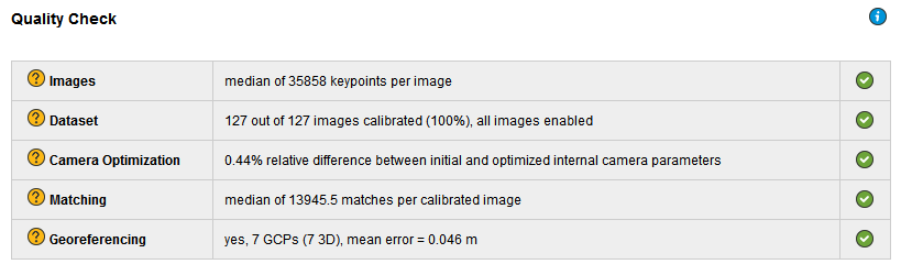
1. Quality Check
Verify that:
- All the checks are green.
- All or almost all the images are calibrated in one block.
- The relative difference between initial and optimized internal camera parameters is below 5%.
- (optional) If using GCPs, the GCP error is below 2×GSD.
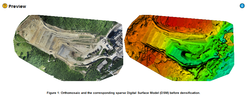
2. Preview
For projects with nadir images and for which the orthomosaic preview has been generated, verify that the orthomosaic:
- Does not contain holes.
- Does not have distortions.
- (optional) If GCPs or image geolocation has been used, it has the correct orientation.
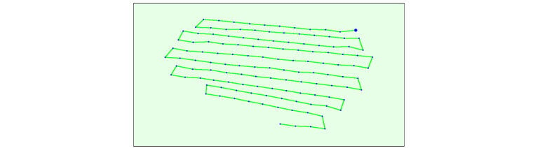
3. Initial Image Positions
(optional) If the images have geolocation, verify that the Initial Image Positions figure corresponds to the flight plan.

4. Computed Image/GCPs/Manual Tie Points Positions
Verify that :
- (optional) If using images with geolocation, the computed image geolocation is good.
- (optional) If using only images with geolocation, the uncertainty ellipses are similar in size.
- (optional) If using GCPs, the GCPs' error is low (the difference between input and computed GCPs is small).
- (optional) If using GCPs and images with geolocation, the uncertainty ellipses are very small, close to the GCPs and may increase for images further away.


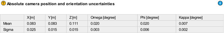
5. Absolute Camera Position and Orientation Uncertainties
Verify that:
- For projects only with image geolocation, the absolute camera position uncertainty is similar to the GPS accuracy, and that the sigma is smaller than the mean.
- For projects with GCPs, the absolute camera position uncertainties are similar to the accuracy of the GCPs.
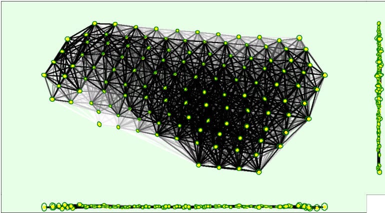
6. 3D Points from 2D Keypoints Matches
Verify that:
- Enough matches have been computed between the images.
- The graph consists of one block. If multiple blocks exist, each block will have a different color.
- The uncertainty ellipses are approximately of the same size throughout the project.
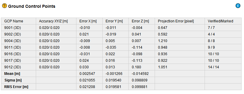
7. Geolocation Details
(optional) If using GCPs, verify that:
- All GCPs are considered (not displayed with red color on the Geolocation and Ground Control Points table).
- All marked GCPs have been verified.
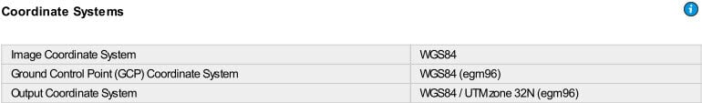
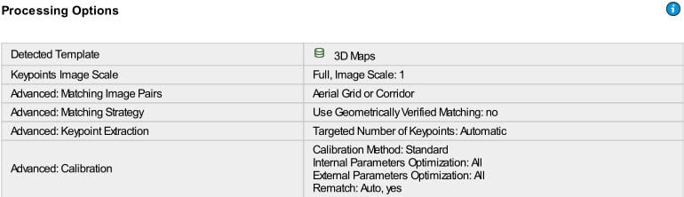
8. Processing Options
Verify that:
- (optional) If using GCPs, the Ground Control Point (GCP) Coordinate System is correct.
- (optional) If using images with geolocation, the Image Coordinate System is correct.
3. Point Cloud and Mesh
To process step 2. Point Cloud and Mesh:
1. On the Menu bar, click View > Processing.
2. The Processing bar opens on the bottom of the main window.
3. Ensure that 2. Point Cloud and Mesh is selected, and that 1. Initial Processing and 3. DSM, Orthomosaic and Index are unselected.

4. Click Start.
4. DSM, Orthomosaic and Index
To process step 3. DSM, Orthomosaic and Index:
1. On the Menu bar, click View > Processing.
2. The Processing bar appears at the bottom of the main window.
3. Ensure that 3. DSM, Orthomosaic and Index is selected, and that 1. Initial Processing, and 2. Point Cloud and Mesh are unselected.

4. Click Start.