To effectively use a PIX4D-supported RTK device with a mobile device, the setup must first be configured correctly. This involves setting the camera offset between the antenna and the mobile device's camera. This offset needs to be manually measured by the user, is crucial for accurately computing locations captured by PIX4D supported RTK devices, ensuring precise measurements for scans or ground control points (GCPs).
IN THIS ARTICLE
Mount the Leica Zeno FLX100 plus RTK rover to the mobile device
Zeno Connect and RTK configuration
RTK profile creation and connection to the RTK Leica device
How to Manually Measure the Camera Offset
Measure the X and Y-axes
Measure the Z axis
The PIX4D supported Leica Zeno FLX100 plus is a GNSS RTK receiver that allows PIX4Dcatch to geolocate the images acquired by your mobile device with centimeter accuracy. The PIX4D supported Leica RTK rover can be coupled with mobile phones (iOS) using the Quad Lock mount provided by Quad Lock.
The following equipment is required to complete this guide:
Hardware:
- Leica FLX100 plus
- Leica FLX100 plus pole mount AZ219
- Leica GLS53 Mini Pole
- iPhone Pro
- Quad Lock case for your iPhone Pro model
- Quad Lock handlebar mount


Software:
- Leica Zeno Connect on iOS.
- PIX4Dcatch on iOS.
Important: Update to the latest version PIX4Dcatch and Zeno Connect (4.3.0) to ensure stable connectivity.
Mount the Leica Zeno FLX100 plus to the mobile device
-
Screw the FLX100 plus to the FLX100 plus pole mount.

- Place the 22.2mm (7/8’) bar spacer on the GLS53 pole.
-png.png?width=157&height=350&name=unnamed%20(20)-png.png)
- Align the bar spacer with the line marked in blue. Make sure that the bar space is NOT aligned with the line marked in orange.

- Mount the FLX100 plus with the pole mount on the GLS53.

- Rotate the opening of the bar spacer so that it is aligned with the left side of the FLX100 plus antenna.

- Attach the Quad Lock mount clamp to the GLS53 pole with the head facing the same direction as the FLX100 plus.

- Attach the extension arm to the handlebar amount clamp so that the extension arm is oriented towards the right side and perpendicularly to the pole.

- Attach the index head to the extension arm. The index head should be oriented left and overlapping the extension arm.

- With yout iPhone in the Quad Lock case, attach it to the Quad Lock handlebear mount.

- Attach the extension arm to the handlebar amount clamp so that the extension arm is oriented towards the right side and perpendicularly to the pole.
When using the Leica FLX100 with Zeno Connect, the system automatically configures the NTRIP provider details for convenience. Alternatively, a custom NTRIP provider can be configured, or the default provider supplied by the Leica Zeno Connect application can be used.
Zeno Connect and RTK configuration
To ensure optimal performance and accuracy, follow these steps:
- Download the Zeno Connect app by Leica from the Apple Store.

- Open the Zeno Connect app, go to the main menu, and select the FLX100 plus.
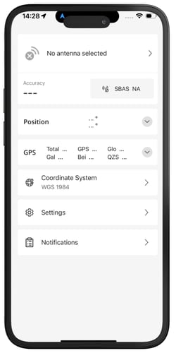

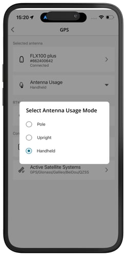
- Navigate to Selected antenna and choose the Antenna Usage: Then, select Handheld for the Antenna Usage Mode. This configuration ensures the system uses the internal antenna of the device for optimal signal reception.
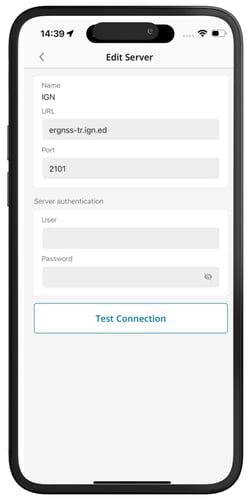
- Select GPS Correction Profiles and click the plus icon to create a new profile. All required fields must be completed. The server must be added to display the list of available mountpoints.
Keep the sliders for Auto Connect and NTRIP activated. After all fields are completed, click Test Connection to verify the configuration.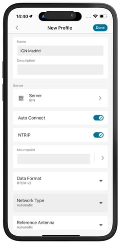
- Go back to the GPS menu and click the NMEA Messages. The settings values are the following:
GGA: Set to transmit 10 times per second (10 Hz). This provides high-frequency position updates for precise tracking.
GSA: Set to transmit 1 time per second (1 Hz). This reports the current satellite configuration for navigation.
GST: Set to transmit 10 times per second (10 Hz). This ensures detailed positional error estimates are frequently updated.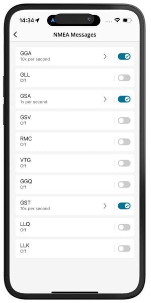
Configuring these settings ensures that the Leica FLX100 operates efficiently and provides accurate positioning data for various applications.
Important: Update to the latest version for PIX4Dcatch and for Zeno Connect
Note: In Zeno Connect, the options to set are:
-
Antenna Usage: Handheld
-
The NTRIP settings
-
NMEA Messages (GGA, GST 10x/sec + GSA - the default can be used)
-
Turn OFF the tilt option (if using the new Leica model)
Setting the input NTRIP CRS in the Zeno Connect app is not required. If configured, however, it must match the CRS defined in the PIX4Dcatch app.
RTK profile creation and connection to the RTK Leica device
To connect your Leica device to PIX4Dcatch, follow these steps:
-
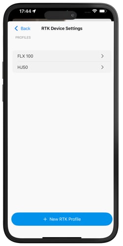
To configure the RTK profile and establish a connection with the RTK antenna, please proceed to the RTK Device Settings section located within the menu and select RTK Device Settings.
.png?width=250&height=500&name=menu%20(2).png)
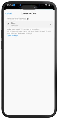
- Click on RTK BLUETOOTH DEVICE to create a new profile

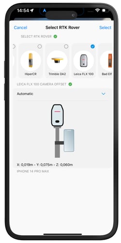
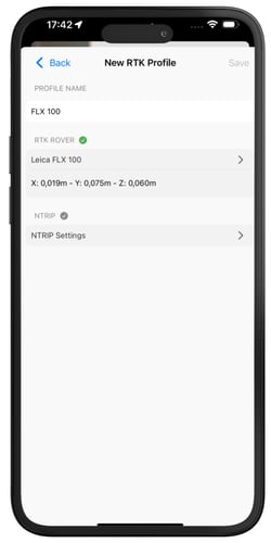
- Fill the PROFILE NAME for the FLX 100, select the RTK rover, and choose Automatic.

- When accessing the NTRIP settings, Leica Zeno Connect opens automatically and displays the current position and accuracy.

- After completing the configuration, reopen PIX4Dcatch and select the FLX100 profile to display the new profile. Then select RTK via Bluetooth to connect the device.
- Within PIX4Dcatch, the Leica device can then be used for precise geotagging and image capture.
This process ensures seamless integration of the Leica device, Leica Zeno Connect, and PIX4Dcatch, enabling accurate positioning data for photogrammetry workflows.
How to Manually Measure the Camera Offset

Place the device in portrait mode and the display to the front. Notate the orientation of the X, Y, and Z axes and how they relate to the point of origin on the antenna to measure from. The point of origin resides in the middle of the screw mount at the base of the antenna. It will also be necessary to determine which lens to measure from for devices with multiple camera lenses.
Measure the X and Y-axes
To measure the X-axis offset, measure the X-axis on the vertical axis from the base of the antenna to the point where it intersects the Y-axis. Then, measure the distance from the camera lens to the center of the antenna.

Measure the Z axis
Measure the depth from the center of the antenna to the center of the lens for the Z-axis offset.

With the camera offsets properly measured and recorded, they can be included in the appropriate Camera Offset Values field of the RTK Device Settings dialog. Depending on the device's geographical region, centimeters or inches will be the displayed measurement unit.
Third-party information disclaimer:
PIX4D provides instructions for third-party platforms and products solely as a helpful guide to unblock your integration. Those companies are independent of PIX4D. We do not maintain, control, or guarantee the performance, accuracy or reliability of these products.
PIX4D may provide third-party links or contact information to help you find additional information about this topic. This contact information may change without notice. PIX4D does not guarantee the accuracy of third-party documentation or contact details.