Drone Transmission Tower inspection mainly focuses on acquiring the necessary images according to a precise flight planning strategy to ensure a complete analysis of the different components and geometries during the upcoming stages.
IN THIS ARTICLE
Requirements
Designing the data acquisition plan
Setting references
Mission list
Signal loss scenarios
General recommendations
3D model missions
Orbit mission
Single vertical mission
Visual inspection missions
Underneath orbit mission
Manual images mission
Requirements
Quality of images
To design a good data acquisition, it is important to ensure images show the greatest possible detail in the structure.
To check if the quality of the images captured is good enough, please refer to the real-time video feedback and the quality of the pictures taken from the drone.
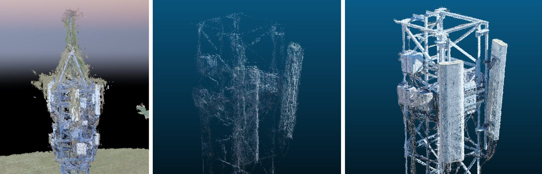
Quality of the scene reconstruction
The final 3D model should meet the following criteria:
- Low noise level.
- Surface definition and defined edges.
- High point density.
- High relative accuracy, including the correct scale, orientation, and verticality of the tower.
Designing the data acquisition plan
Flight planning depends on the tower structure, the number of points of interest, specific site requirements, and tower dimensions.
Our general recommendation for a full Transmission Tower reconstruction is to fly one Orbit mission at the top of the structure and at least six Single Vertical missions (three on each side of the structure).
The Orbit mission increases the model quality at a specific level, so apart from the Orbit on top of the structure, we recommend adding an Orbit mission per point of interest as long as it is safe and the nature of the structure allows it.
Single Vertical missions provide global tower reconstruction and verticality.

Setting references
The Transmission Tower asset locations are based on some references recorded by the operator after taking-off and while piloting the drone in the air manually.
After selecting the Transmission Tower asset mission in the new plan creation window, follow the onboarding guide and determination of the Transmission tower center, and the Transmission tower highest point.
Set the Transmission tower center
This is done to be as accurate as possible to get the center reference of the transmission tower to be scanned, warranting that all the flights within the same transmission tower asset will share the same center position.
If Return to Home (RTH) height is lower than the current drone height when setting the center reference, a pop-up dialog will ask the user to confirm to update that value to the current height. This way, the RTH will be a safe, known height higher than the tower to avoid potential collisions in case of an RTH.
An animated description will guide the user to determine the transmission tower center reference:
- Place the drone on top of the tower (several meters above for safety).
- Ensure height is higher than 10 m.
- Ensure the camera angle is -90°, or tap on Set to -90o.
- Point the camera at the center of the tower.
- Tap on Next to confirm the current tower center reference.
Set the Transmission tower highest point
The next step is to determine the Transmission tower highest point. This value is used for planning Single Vertical missions.
An animated description will guide the user to determine the transmission tower highest point reference:
- Align the drone with the highest point of the tower.
- Ensure the drone height is higher than 10 meters.
- Ensure the camera angle is 0°, or tal on Set to 0o.
- Point the camera at the top of the tower.
- Tap Next to confirm the current tower highest point reference.
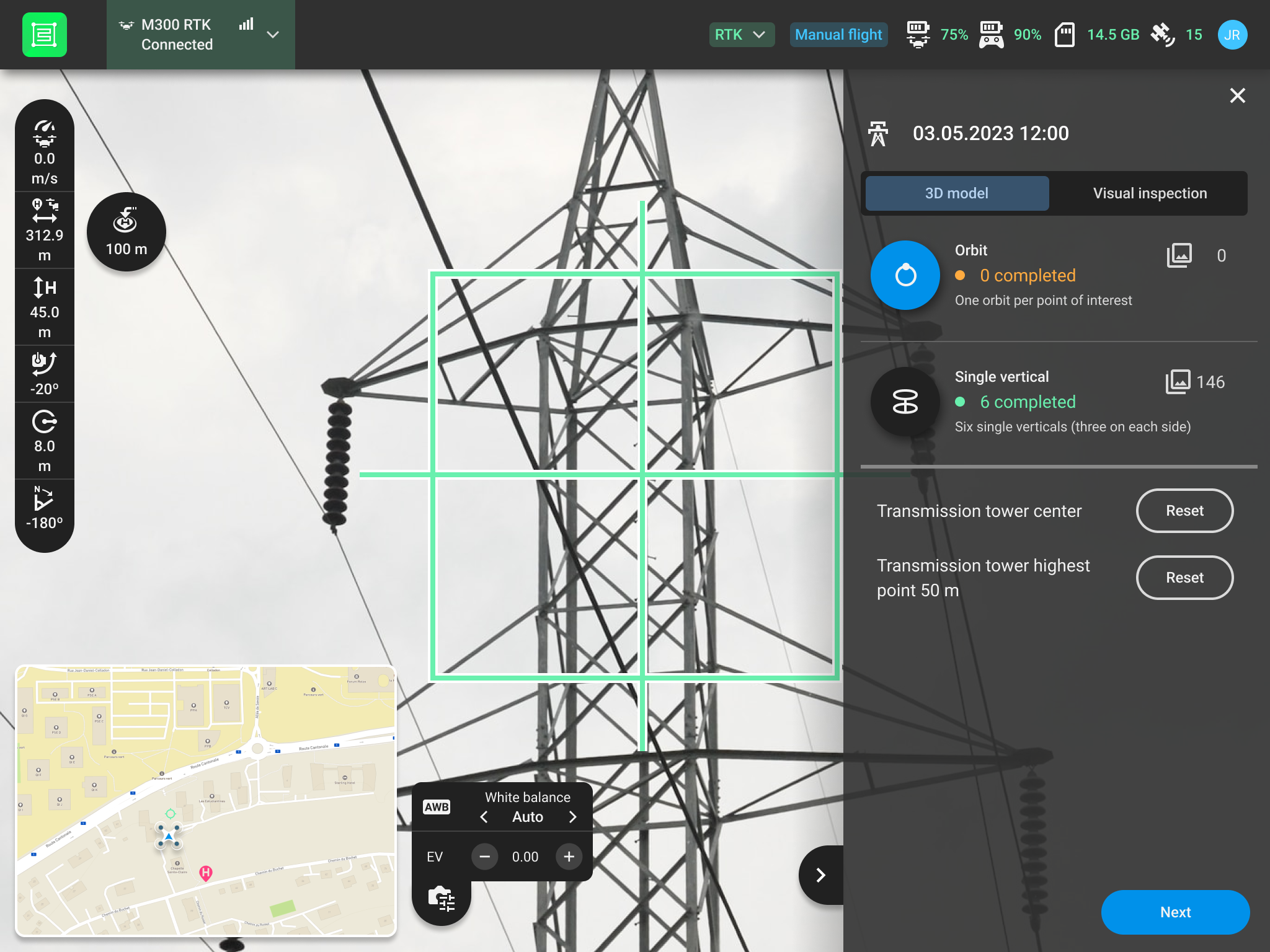
Mission list
When the transmission tower references have been set, the mission list is displayed. It is divided into 3D Model and Visual inspection categories containing all the missions to reconstruct and inspect transmission tower assets efficiently.
It also shows the transmission tower reference values recorded at the previous stages and provides the ability to reset them. Select one of the missions and tap Next to enter the mission settings. After finishing any of the missions (except Single vertical), the Transmission tower mission list is displayed, showing the number of finished missions and the total number of images or videos for each mission type. It is then possible to execute another mission by selecting it and tapping Next or to exit the mission list by tapping on the cross  at the top right side.
Signal loss scenarios
The PIX4Dcapture Pro missions are specially designed to deal with signal loss scenarios, as it can be a common case. If the signal is lost during a mission, the drone will continue flying the mission and triggering the images. If once the mission is finished, the signal is not back, then the drone will execute the selected signal lost action (RTH, Hover, Land). This ensures the integrity of the data.
General recommendations
In order to obtain optimal results, please make sure to follow our recommendations:
- Calibrate the drone sensors (compass, IMU, etc.) if you are flying in a new location.
- Place your drone take-off position at least 20m away from the upcoming mission flight path in a safe place.
- Ensure you have a strong GPS signal (wait one minute before taking off for the first time or after every battery switch).
- Do not close PIX4Dcapture Pro while performing a mission.
- Keep the radius as constant as possible for all the missions performed.
3D Model missions
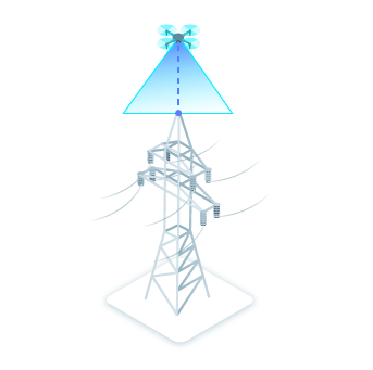
Orbit mission
The main goal of the Orbit mission is to acquire images with high overlap around the point of interest.
In order to get an optimally reconstructed digital twin, it is recommended to perform 1 Orbit mission above the tower and to increase the number of images in the most interesting areas. Orbits can be executed at any level where the user wants to have a higher definition/density in the digital twin.
In the case of transmission Towers, we also recommend performing 1 Orbit mission per point of interest as long as it is safe and the nature of the structure allows it.
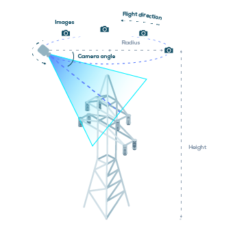
Rather than selecting them from the mission settings, values such as Camera angle, Radius, and Height are based on the video feed on the screen, so from the current drone position, which is manually adjusted with the drone's controller. This is to ensure that we are viewing what we are going to scan, so having a correct point of view for the orbit images.
The following parameters can be adjusted.
Time interval capture: time-optimized continuous flow
Stop at capture point: stability and image centering optimized flow
Time interval capture
Flight direction allows users to define the direction of a circular mission
Clockwise or Counterclockwise
Mission truncation allows users to define a truncation angle for the mission, providing flexibility in mission design
0o - 315o
* Recommended value is based on a 2 m radius structure. If the structure is wider, then the radius should be increased accordingly.
** Different capture modes are supported for DJI drone
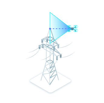
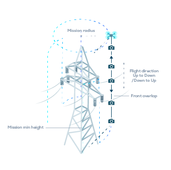
Single vertical mission
The dashed circle in the map view represents the selected radius. When the drone moves around the point of interest, the starting position of the Single vertical is dynamically projected over it. Once a Single vertical has been completed, the user remains in the mission view, and a green check appears on its location as a visual reference for upcoming Single verticals.
The following parameters can be adjusted.
Down to Up
* If multiple Single vertical missions are performed, it is recommended to use the same radius.
The following values are automatically calculated:
- Camera angle: Values will be interpolated along each vertical between -45o at the mission maximum height and the resulting value from looking at the tower base from the mission minimum height.
- The Max flight height: Maximum height for the drone to fly. The drone will start the first line from the top, at a height of Mission max height = Cell tower highest point + mission radius.
Visual inspection missions
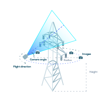
Underneath orbit mission
It is designed to get high-quality images from the lower side of the connection board, cables, etc. Basically, the strategy is the same as for the orbit mission (1 Underneath orbit mission per point of interest as long as it is safe and the nature of the structure allows it. ) but with a lower number of images.
The following parameters can be adjusted.
Manual images mission
The Manual images mission is meant to control the drone with the remote controller and take images from custom points of view.