


Mesh
Note: since version 2.4.0, processing can be paused and resumed at any time as long as the project remains open. There is no need to cancel and start over. If processing is paused and the project is about to be closed, the following message will appear.

IN THIS ARTICLE
Post version 1.77Input
Quality
Template
Deghosting
Model simplification
Polygon-aware
Interior improvement
Sky mask
Mask-aware
Exports
Prev version 1.77
Pipeline
Texture size
Decimation
Smoothing
The following processing options can be adjusted when enabling the mesh generation
- Click Process
 .
. - On the Menu bar, click Process > Mesh...
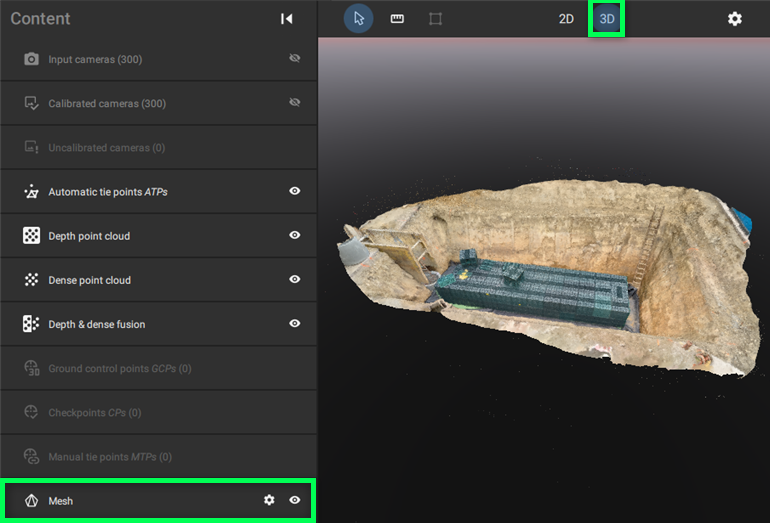
- In the menu bar, click View > Switch to 3D, or
- Click the 3D button on the screen
 , or
, or - Use shortcut 3.
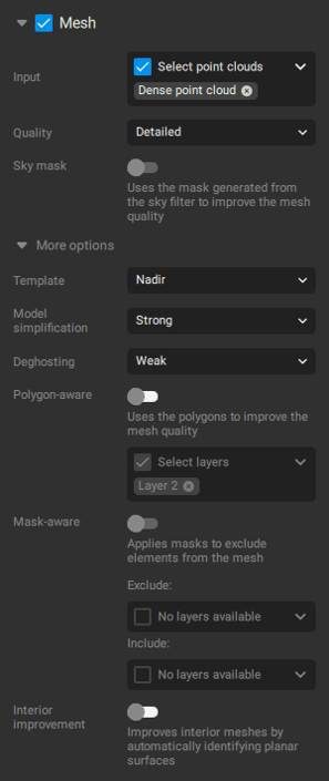
Input
It allows selecting the input point cloud for the Mesh generation. The following options are available:
- Dense point cloud (default): The point cloud generated from images during the Densify step.
- Depth point cloud: The point cloud generated from LiDAR depth maps.
- Depth & dense fusion: The point cloud that presents a fusion of the dense and depth point cloud.
Important: In case the input is not selected, the start button is not enabled, and a warning message will appear in the processing panel.
![]()
Quality
Defines the trade-off between processing time and mesh detail.
- Detailed: Produces the highest-quality mesh, with maximum detail. Recommended when accuracy and visual fidelity are priorities.
- Preview: Optimizes for faster processing at the cost of reduced mesh quality. Suitable for quick previews or low-priority outputs.
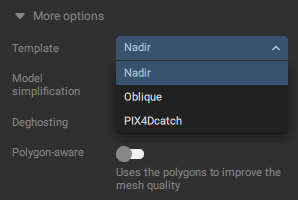
Template
This option enables distinguished default parameters for the mesh generation algorithms used for the different types of datasets imported into the software. The following templates are available for the Mesh generation:
- Nadir. Optimized for nadir aerial data.
- Oblique. Optimized for oblique aerial data.
- PIX4Dcatch: For projects with limited extent. Optimized for hand-held captured data with PIX4DCatch.
Model simplification
Controls the level of mesh decimation to reduce file size and complexity while balancing detail.
- Weak: Preserve finer details. Recommended for captures of close objects.
- Moderate: Simplify finer details. Recommended for generic PIX4Dcatch scenes or merged projects containing PIX4Dcatch data.
- Strong: Stronger simplification. Recommended for nadir scenes.
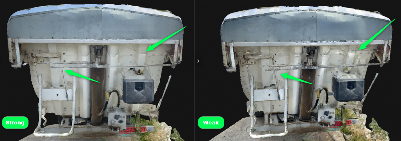
Deghosting
This setting adjusts the parameters used during mesh generation to handle outliers and improve results in complex scenes. It can help remove unwanted objects or artifacts, particularly in datasets with high geometric complexity or motion.
The following deghosting modes are available:
- Weak (default): Suitable for general use. Applies mild outlier filtering, which helps in most cases. However, it may introduce artifacts around thin structures (e.g., cables, antennae) or moving objects.
- Strong: Applies more aggressive outlier filtering. Recommended for highly complex geometry (e.g., telecom towers) or scenes with significant motion (e.g., crowded streets). This setting may reduce color saturation and sharpness in some areas.
Polygon-aware
This option, when selected, enables the use of polygons to improve the mesh quality. It is possible to select or deselect the desired layers, that have been created in the project. This option is only enabled when at least one polygon is created and associated with a layer.
Important: The mesh should be generated or reprocessed after editing a polygon.
PIX4Dmatic allows for the manual creation of polygons. To create these features, ensure that a point cloud is visible, click on Tools, and select Polygon. Alternatively, the keyboard shortcut P can activate the tool. Once activated, vertices will snap to the point cloud, MTPs, or ITPs. Left-click to add vertices. Right-click to add the final vertex and complete the polygon.
After creating the polygon, the following options are available by right-clicking:
- Invert selection
- Delete polygon
- Move to layer
- Flip face orientation
- The face orientation indicates the direction in which the faces of the polygon are oriented. This option can be enabled via Settings > Viewing option. Correctly setting the direction of the faces provides for a better mesh reconstruction and viewing experience. It is essential that the faces of the polygon are oriented toward the direction of the cameras used during image capture. To adjust face orientation, right-click on the plane and select Flip face orientation.

- The face orientation indicates the direction in which the faces of the polygon are oriented. This option can be enabled via Settings > Viewing option. Correctly setting the direction of the faces provides for a better mesh reconstruction and viewing experience. It is essential that the faces of the polygon are oriented toward the direction of the cameras used during image capture. To adjust face orientation, right-click on the plane and select Flip face orientation.
- Set polygon to planar
- Set polygon to non-planar
- Create section from polygon
Interior improvement
When creating and editing Planes for interior scenes, it is recommended to use the Backface culling feature in the Settings. When enabled, this feature allows for backward transparency for the Planes. The Plane will be opaque when viewed from the front. However, it will be transparent when viewed from behind. This allows for an obstructed view of interior scenes.
 |
 |
Sky mask
Sky mask utilizes the generated mask during the Dense point cloud step to improve the mesh quality. It is enabled by default when the Sky filter option is enabled while running the Dense point cloud step.
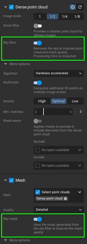
Mask-aware
Masks can be applied during mesh generation to exclude elements from the resulting meshExports
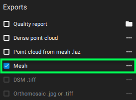
From the Exports section, the following can be exported after processing the Mesh step:
- Point cloud from mesh .laz
- Mesh
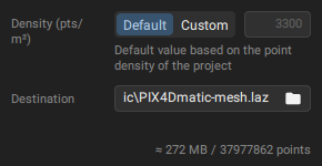
Pointcloud from mesh .laz
PIX4Dmatic allows the generation and export of a point cloud derived from the mesh. During export, users can select the Default point density (pts/m³) or define a Custom value. The expected file size and total number of points are displayed before export. This process enables the creation of a complete point cloud, including areas that were not directly reconstructed, effectively filling any gaps. The resulting point cloud is exported in compressed .laz format.
Mesh
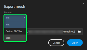
The following formats are available when exporting the Mesh:
- obj (default): PIX4Dmatic exports a Mesh obj that is not georeferenced. It has coordinates in a local coordinate system (Export CRS: Default) centered around the project. With some external viewers, it is possible to add an offset.xyz file to correctly position the Mesh. Once completed, the Mesh will have the same precision as the mesh viewed in PIX4Dmatic. The project_name_offset.xyz file contains the offset of the project and is stored in the folder with the .obj file. The export CRS can also be selected as the Project CRS.

Starting from version 1.80, it is possible to export the mesh in OBJ format, with the option to select either a single file or a tiled export. Additionally, it is possible to select the level of detail, from 0 to 9, changing the number of triangles that will be exported.
- .ply: When this format is chosen, the texture coordinates can be picked between per face and per vertex. Meshes with per vertex coordinates can be imported in Blender and Meshlab. Meshes exported with per face coordinates can be imported into Meshlab.
- Cesium 3D Tiles: The Cesium 3D Tiles are georeferenced. This format allows the Mesh to be easily shared and displayed across many third-party software and 3D platforms. The primary purpose of 3D Tiles is to improve the streaming and rendering performance of massive heterogeneous datasets. The foundation of 3D Tiles is a spatial data structure that enables Hierarchical Level of Detail (HLOD). When selecting and exporting the Cesium 3D Tiles a .json file and various .b3dm files are generated inside the folder project_name-cesium_mesh.
- slpk: A Scene Layer Package (SLPK) file is an openly published file format for 3D geospatial data, designed as a package for storage or exchange that captures all resources for a "scene layer" structured according to the Indexed 3D Scene Layer (I3S) specification. Mesh (LOD) can be exported as .slpk for ESRI compatibility. The SLPK Mesh file is geo-referenced, and the exported multi-LOD mesh in .slpk format is named project_name-mesh.slpk.
- fbx. This is a 3D file format used to store and exchange complex 3D data. It supports geometry, and textures. making it suitable for transferring entire 3D scenes with third-party software.
- Texture size. The value ranges from 1024 × 1024 to 16384 x 16384 pixels
- Level of detail. Number of triangles to be exported (from 0 to 9)
Note: Exporting the mesh to SLPK requires the horizontal CRS to have an EPSG code, and the vertical CRS being ellipsoidal heights or having an EPSG code as well
Note: Texture will not displayed with MeshLab.
INFO
- Please be aware that the option to export to the SLPK format is not available in versions 1.75.0 and 1.76.0.
- The mesh is exported tiled from version 1.77.0 to 1.79.0
Pipeline
Important: From version 1.77, the standard pipeline is no longer available.
Determines the algorithm used for Mesh generation, based on project size and data type.
- Standard (default prior to version 1.77): Designed for efficiency and accuracy across a range of project sizes using nadir and oblique imagery.
- Associated options: Pipeline, Texture Size, Decimation, and Smoothing.
- Scalable: Optimized for large-scale projects, such as city-wide or drone flight-scale models, primarily using nadir imagery.
- Associated options: Model Simplification and Quality.
Texture size
Specifies the resolution of the mesh texture. The value ranges from 1024 × 1024 to 32768 × 32768 pixels, with a default of 8192 × 8192 pixels. Higher values result in more detailed textures but increase memory usage and processing time.
Decimation
Important: From version 1.77, the decimation parameter is no longer available.
Decimation (1,000,000 default): The maximum number of triangles in the final Mesh. The number will depend on the geometry and the size of the project.
Note: For smaller projects, the number of generated triangles may be lower than the maximum defined in the settings. The specified maximum is only reached if the dataset is large enough to support a more detailed model.
The final number of Triangles created during the Mesh can be found in the project log files:
[Decimate mesh geometry](Info) Triangle count: ######
- In the Status center, under the Decimate mesh geometry step:

Smoothing
Important: From version 1.77, the smoothing parameter is no longer available.
This option, when enabled, affects the mesh geometry and applies a smoothing effect to the generated mesh.
Tip: Enable this feature for large-scale projects with a high triangle count to improve performance. For scenes with relatively few triangles, it is recommended to keep this setting disabled.