In this approach, the camera is not moving but it is fixed and the object is rotating on a turntable with visual markers.
IN THIS ARTICLE
Preparation
-
Download the PIX4D visual markers from here.
-
Print the PIX4D visual markers on non-glossy paper. The diameter of the circle enclosing the markers should be around 30 cm.
-
Wrap a turntable with the printed paper.
-
Place a roll of white soft cardboard behind the turntable to hide the background.
-
Mount the camera on a tripod to ensure that it will be steady during the acquisition.
- It is recommended to use a lens with fixed focal length to minimize the parameters that need to be optimized during processing.
- The deeper depth of field can be achieved by selecting aperture around f25.
- It is recommended to illuminate the scene with a source of diffused light to maximize the texture of the object and to reduce the reflections.
Image acquisition
-
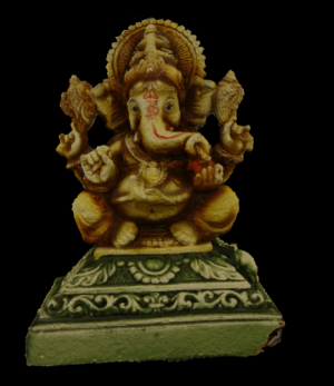
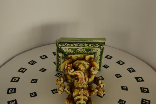
Orient the turntable so that the small arrow in the center of the turntable points away from the camera, as in the image below.
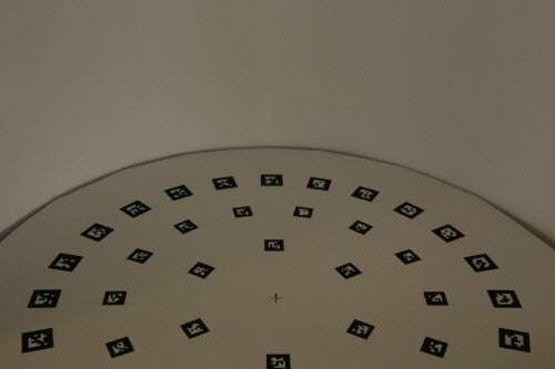
Information: This arrow gives the direction of the y-axis of the local coordinate system and will allow the model to be reconstructed facing towards the viewer. - Place the object on the turntable.
- Capture the first image.

- Rotate the turntable by approximately 15 degrees and take a picture. The next marker of the exterior ring should be in front of the camera.
- Repeat step 4 until one full rotation of the object is completed.
- Turn the object and place it on the turntable again.
- Repeat steps 1 to 6 to capture a second dataset from another point of view to fully reconstruct the object. Capture as many datasets as needed to capture the object completely.
Image processing
- Using the PIX4Dtagger to generate the .p4d project file
- Using PIX4Dmapper to process the subprojects
- (optional) Using PIX4Dmapper to merge the subprojects
Using the PIX4Dtagger to generate the .p4d project file
-
Open the PIX4Dtagger. PIX4Dtagger has been installed with PIX4Dmapper from version 2.2 up to 4.5.6. The PIX4Dmapper 4.5.6 installation file is available to download here. The executable is located in the same folder as your PIX4Dmapper executable (PIX4Dmapper.exe). Therefore, its location will depend on where you installed PIX4Dmapper. For example, this could be: C:\Program Files\Pix4Dmapper
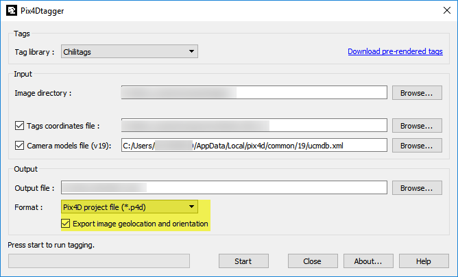
- In Image directory, click Browse... and select the directory where the images are stored. Use PIX4Dtagger for one subproject at a time.
- In Tags coordinates file, click Browse... and select the *.csv file in which the tags that were used in the project and their corners are stored. The file can be downloaded from here.
Important: The coordinates of the visual markers are computed for a turntable where the big markers measure 1.6X1.6 cm and the small markers measure 1.2X1.2 cm. If the printed markers are of different dimensions, the object will be modeled without a real scale. In that case, a scale constraint can be added after Step1 has been processed: How to scale a project - In the Camera models file, click Browse... and select the camera database in: C:\Users\Your Username\ AppData\Local\pix4d\common.
Important: In case the camera is not included in the Pix4D camera data base, it should be saved into it when creating the project: Menu Project > Image Properties Editor... > Selected Camera Model > Edit Camera Model - In Output file, click Browse... and select the name of the output file and where it should be stored.
- In Format, select Pix4D project file (*.p4d) and make sure that Export image geolocation and orientation is selected. PIX4Dtagger is able to compute exterior orientations based on the tag ́s coordinates. These exterior orientations will be used as initial values during the standard Pix4D process and they will help in the reconstruction.
- Click Start to start exporting the project file.
- Repeat steps 1-7 for each dataset captured.
- Click Close to close PIX4Dtagger.
Using PIX4Dmapper to process the subprojects
-
Open each of the subprojects generated in PIX4Dmapper by double-clicking it.
-
In the Processing Options of step 1. Initial Processing, in the Matching Image Pair section of the Matching tab, select Free Flight or Terrestrial: Menu Process > Processing Options... > 1. Initial Processing > Matching.
-
In the Processing Options of step 1. Initial Processing, in the Calibration tab, select Accurate Geolocation and Orientation calibration method: Menu Process > Processing Options... > 1. Initial Processing > Calibration.
-
In the Image Properties Editor window, edit the Accuracy Horz and Accuracy Vert values to 0.10 m. For more information: Menu Project > Image Properties Editor... > Images Table.
-
Process step 1. Initial Processing.
- Repeat steps 1-5 for each subproject generated.
Information: The default Accuracy Horz and Accuracy Vert values are 5 and 10 meters respectively, but they do not make sense for this application where the object size is just a few cm big.
Using PIX4Dmapper to merge the subprojects
Note: This applies if more than one subprojects are captured. If only one subproject is captured, continue with step 2. Point Cloud and Mesh to generate the Point Cloud and the 3D Textured Mesh.
-
Clear the image geolocation of the images by clicking Clear in the Image Geolocation section of the Image Properties Editor: Menu Project > Image Properties Editor... > Image Geolocation.
-
Remove all GCPs of the visual markers from the subproject: GCP / Manual Tie Point Table.
-
Mark at least 3 Manual Tie Points in the common area between the subprojects. The common MTPs should share the same name in all the subprojects that they appear.
Important: In case there are more than 2 subprojects, it is not mandatory for all of them to share the same common area, but each subproject should share a common area and at least 3 MTPs with the adjacent one. - Repeat steps 1-3 for all subprojects.
- Merge the subprojects following:Merging projects.
- Process step 2. Point Cloud and Mesh for the merged project.
- (optional) Edit the point cloud to remove the points of the visual marks reconstructed, following: How to edit the point cloud in the rayCloud.
- (optional) Regenerate the 3D Textured Mesh without the visual marks, following: How to generate the 3D Textured Mesh (section: After processing step 2. Point Cloud and Mesh).