- Installation
- Tags
- Input
- Output
- Status bar
- Command line
- Manual Tie Points (MTPs)
- Ground Control Points (GCPs)
- Use the outputs in PIX4Dmapper
PIX4Dtagger can automatically detect specific tags in images and generate output files that include marks for manual tie points (MTPs) or ground control points (GCPs). The main applications are:
- Creation of a camera calibration workflow
- Indoor photogrammetry
- Object modelling
- Close range/low altitude mapping (less than 30 meters)
Installation
PIX4Dtagger had been installed with PIX4Dmapper from version 2.2 up to 4.5.6. The PIX4Dmapper 4.5.6 installation file is available to download here. The executable is located in the same folder as your PIX4Dmapper executable (PIX4Dmapper.exe). Therefore, its location will depend on where you installed PIX4Dmapper. For example, this could be: C:\Program Files\Pix4Dmapper .
Tags
PIX4Dtagger supports only the tags of the library Chilitags. To download the tags click here.
These visual markers are square tags with a black border around the data matrix which encodes their ID and an external white border. Each tag has a unique ID and should be used only once in a project.
For an optimal detection of tags in the images, the tags should:
- Have a unique ID. Do not use the same tag twice in a project.
- Have a white border which is at least as wide as the black border.
- Must not be occluded by another object or the environment.
- Have a recommended size of about 50x50 to 100x100 pixels in the images.
Practically, if the distance to the tag is of about 10 meters, the tag can safely be printed on an A4 size sheet. If the distance is of about 50 meters and a camera such as a GoPro is used, then the GSD would be of about 1cm and the printing size is recommended to be 1x1m. Flying with a Canon Ixus at 100m distance would require a 1.5x1.5m surface. The size at which the tags should be printed depends on the camera, lens and image quality.
It is recommended to print the tags on non-reflective material.
The corners of a tag are numbered clockwise from 0 to 3 based on the original position of the tag in the Chilitag library:
- Corner 0: top left (marked in red in the example image below)
- Corner 1: top right
- Corner 2: bottom right
- Corner 3: bottom left
PIX4Dtagger is able to identify the numbers of each corner (defined by the original position) even if the tag is oriented differently when captured in an image.

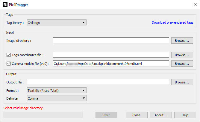
Input
These are the inputs that can be specified:
Image directory: The path leading to the folder containing the images that should be tagged.
Tags coordinates file (optional): In this file, the tag ID, the tag corner and its coordinates can be defined. There are two possible input formats:
- ID, corner, x, y, z
Example: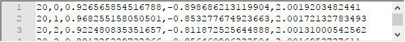
Line 1 identifies tag no. 20, corner 0, x=0.926565854516788, y=-0.898686213119904, z=2.0019203482441. - tag_ID_corner,x,y,z
Example: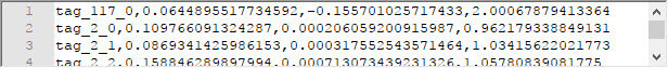
Line 1 identifies tag no. 117, corner 0, x=0.0644895517734592, y=-0.155701025717433, z=2.00067879413364.
For both:
ID being the number written on the downloaded tag files.
ID being the number written on the downloaded tag files with the "tag_" prefix".
corner being the corner number of the tag (0,1,2,3).
x, y and z being the coordinates of the corner of that particular tag, measured on the field (with a scanner, a total station, a geodesic GPS or a previous reconstruction).
If several tags are identified, each should be written on a separate line.
Camera models file (v19) (optional but recommended): Knowing the camera model that was used to take the images increases the accuracy of marks for perspective, fisheye and spherical cameras. PIX4Dtagger is compatible with version 19 and newer of the PIX4Dmapper database. Select the file icmdb.XML in the following path: C:\Users\Your Username\ AppData\Local\pix4d\common\19
Output
PIX4Dtagger can generate these output files:
- Text file (.csv, .txt): File with marks that can be imported to PIX4Dmapper in Project > GCP/MTP Manager.
- Bingo file (.txt): File with marks that can be imported to PIX4Dmapper in Project > GCP/MTP Manager.
- PIX4D project file (.p4d): Creates a .p4d file that includes the GCPs or MTPs that can be opened with PIX4Dmapper. Note that if files are provided for Tags coordinates file and Camera models file (v19), it is possible to export an initial estimate of image geolocation and orientation. The latter is most useful when no GPS information or low accuracy GPS information is available.
Status bar
At the bottom of PIX4Dtagger, a status bar displays the state of the tagging once it was started (error message, or percentage of the process completed).
Command Line
PIX4Dtagger can be used in the command line. For more information on the available options:
- Open the command line
- For more information, enter the command: pix4dtagger.exe -h
Manual tie points (MTPs)
This is a possible workflow to automatically create MTPs:
- Dispatch the tags in the area of your project.
- Acquire images of your area. Make sure that each tag is visible in several images. Create a directory and store the images inside.
- Open PIX4Dtagger.
- Next to Image Directory, click Browse... and select the directory where the images were stored
- (optional) Next to Tags coordinates file, click Browse... and select a .csv file where the tags that were used in the project and their corners are stored.
- (optional but recommended) Next to Camera models file, click Browse... and select the camera database in: C:\Users\Your Username\ AppData\Local\pix4d\common
- Next to Output file, click Browse... and select the name of the output file and where it should be stored.
- Select the Format (Text file, Bingo file, p4d file). If Text file is selected, the Delimiter can be selected (Comma, Semicolon, Tab, Space).
- Click Start to run the automatic tagging, which will create the selected output format.
Ground control points (GCPs)
This is a possible workflow to automatically mark GCPs:
- Dispatch the tags in the area of your project.
- Measure some corners of the tags (using a scanner, a total station, a geodesic GPS or a previous 3D reconstruction).
- Write the measurements into a .csv file.
- Acquire the images. Make sure that each tag is visible in several images. Create a directory and store the images inside.
- Open PIX4Dtagger.
- Next to Image Directory, click Browse... and select the directory where the images were stored.
- Next to Tags coordinates file, click Browse... and select the file defined in step 3).
- (optional but recommended) Next to Camera models file, click Browse... and select the camera database in: C:\Users\Your Username\ AppData\Local\pix4d\common
- Next to Output file, click Browse... and select the name of the output file and where it should be stored.
- Select the Format (Text file, Bingo file, p4d file). If Text file is selected, the Delimiter can be selected (Comma, Semicolon, Tab, Space).
- Click Start to run the automatic tagging, which will create the selected output format.
Use the outputs in PIX4Dmapper
The way to use the outputs created by PIX4Dtagger depends on the output format.
If a .p4d file was generated:
- Open PIX4Dmapper.
- Click Project > Open Project...
- The project has the Tie Points (MTPs or GCPs) directly imported and marked in the images.
If a text file or Bingo file was generated.
- Open PIX4Dmapper.
- Click Project > GCP/MTP Manager > Import GCPs...
- Select the .txt or .csv file that was created by PIX4Dtagger.