Access: On the Menu bar, click View > Volumes to open the Volumes view. The sidebar is displayed on the left of the main window. The Volumes view is available when the point cloud and the DSM are generated.
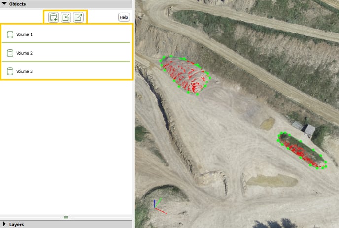
The Objects section consists of two parts:
Action buttons
There are 3 action buttons:
 New volume: Allows the user to draw a new volume. For step by step instructions: How to draw a Volume.
 Import volume: Opens the Import Volume pop-up that allows to import volumes created previously with PIX4Dmapper or created manually for the same area of study. For step by step instructions: How to import a Volume into Volumes.
Important:
- To import a volume created previously with PIX4Dmapper, it has to be a .shp file that contains surfaces (name_surfaces.shp) or vertices (name_vertices.shp).
- To import a volume created with an external software, it has to be a .shp file that contains a 3D polygon (surface) or 3D vertices.
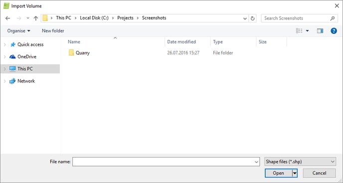
It contains the sections:
- Navigation window: Used to search and select the file to be imported.
- File name: Displays the name of the selected file to be imported.
- Files of type: Displays the possible formats accepted for the input file: Shape files (.shp) are accepted.
And the action buttons:
- Open: Imports the selected file.
- Cancel: Does not import the Volume and exits the pop-up.
 Export volume: Allows the user to select and export the volumes the following buttons appear:
- Select: Allows the user to select All or None of the volumes to be exported. The user can also select some of the Volumes to be exported by selecting the box that appears next to the names of the volumes.
Important: At least one volume needs to be selected to be exported.
- Cancel: Cancels the export of volumes.
- Export: Opens the Export pop-up:
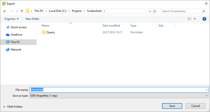
It contains the sections:
- Navigation window: Used to search and select the directory in which the volume will be exported.
- File name: Allows the user to select the name of the file to be exported.
- Save as type: Displays the possible formats accepted for the input file:
- AutoCad DFX (.dfx).
- ESRI Shapefiles (.shp).
- Keyhole Markup Language (.kml).
- Microstation DGN (.dgn).
Volume list
It contains the list of volumes added to the project and the measures for each volume.
Important: The volume is computed between the volume's base and the surface defined by the DSM generated in step 3. DSM, Orthomosaic and Index.
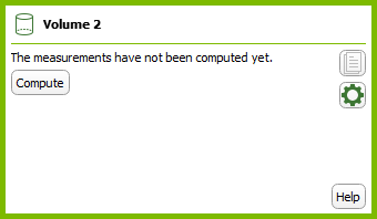
The volume information is displayed by clicking the volume name in the Objects layer of the sidebar.
Important: The volume information is displayed once the volume is computed. If the volume is not computed, the Compute button will appear. Clicking the Compute button will compute the volume.
The following information is displayed:
- Volume name: The name of the volume.
- Terrain 3D Area [units2]: Area that is defined by the DSM included in the volume's base.
- Cut Volume [units3]: Volume that is above the volume base. The volume is measured between the volume's base and the surface defined by the DSM.
- Fill Volume [units3]: Volume that is below the volume base. The volume is measured between the volume base and the surface defined by the DSM.
- Total Volume [units3]: Total volume, Total Volume = Cut volume + Fill volume.
Tip: For more information on the error estimation (+/-) in volume calculation: Which Base Surface is recommended for the Volume Calculation?.
When hovering over one volume, 2 action buttons appear:
 View/Hide: Allows to view or hide the volume from the 3D view.
 Delete: Allows the user to delete the volume.
When selecting a volume, 3 action buttons appear:
 Compute: Computes the volume selected. Appears when the volume is not computed, when there is a change in the name or in the base surface of the volume or the DSM.
 Copy to Clipboard: Copies the measures of the selected volume to the clipboard that can be pasted into a text editor or spreadsheet by opening the destination file and pasting.
 Settings: Allows the user to select the base surface settings and the display settings of the volumes. The Volume Settings pop-up appears.
It consists of two tabs:
- Base surface Settings: Allows to select the base plane for the volume calculation. There are six different options:
- Triangulated: Selected by default. Connects all the vertices and triangulates the volume above and below the base surface. Recommended option when the entire boundary of the stockpile is visible and the surface is relatively flat.
- Fit Plane: Fits a plane to the vertices, so that all vertices are at the minimum distance from the base surface. Recommended option when the entire boundary of the stockpile is visible and the base surface is a hard surface, a slope or flat with the same altitude.
- Align with Average Altitude: The base surface is parallel to the XY plane with altitude at the average altitude of all vertices.
- Align with Lowest Point: The base surface is parallel to the XY plane with altitude at the lowest altitude of all vertices. Recommended option when part of he boundary is not visible, for example the stockpile is partially surrounded by walls.
- Align with Highest Point: The base surface is parallel to the XY plane with altitude at the highest altitude of all vertices. Recommended option when the desired computation is the fill volume of a bunker, a pool, a pond, etc.
- Custom Altitude [units]: The base surface is parallel to the XY plane with altitude at a custom altitude. Recommended option when the stockpile is surrounded by walls and only part or even no boundary is visible, but the altitude of the flat base surface is known.
Tip: For more information and specific cases about how to choose the base surface settings: Which Base Surface is recommended for the Volume Calculation?.
- Display: Allows to edit the display properties for one or all the volumes.
- Vertex Color: Color of the spheres that represent the vertices of the bases of the volumes.
- Vertex Radius: Radius of the spheres that represent the vertices of the bases of the volumes.
- Line Color: Color of the lines between the vertices of the bases of the volumes.
- Line Width: Width of the lines defining the bases of the volumes.
- Base: View/hide the bases of the volumes.
- Color: Color of the bases of the volumes.
- Shader: Specifies the way each triangle of the bases of the volumes is colored. The color is related to the 3D position of each triangle. There are 2 ways of coloring the triangles available:
- Monochrome: Selected by default. The triangles are colored with a color-to-black scale depending on the angle with respect to a virtual sun positioned in the north-east at 45 degrees from the horizon. It uses the color selected above.
- Color: The triangles are colored with an RGB scale. The color of a triangle depends on the angle with respect to 3 virtual suns with Red, Green, and Blue illumination. The color of each triangle is the combination of the light received by the 3 virtual suns. This shader gives a slope map if the model is looked at from top. It gives information about the orientation of each surface.
- Terrain: View/hide the triangles defining the terrain. These triangles are generated using the base of the volume and the DSM and below that surface.
- Color: Color of the triangles defining the terrain. These triangles are generated using the base surface and the points above and below that surface (this property only affects Volume objects).
- Shader: Specifies the way each triangle defining the terrain is colored. The color is related to the 3D position of each triangle. 2 ways of coloring the triangles are available:
- Monochrome: Selected by default. The triangles are colored with a color-to-black scale depending on the angle with respect to a virtual sun positioned in the north-east at 45 degrees from the horizon. It uses the color selected above.
- Color: The triangles are colored with a RGB scale. The color of a triangle depends on the angle with respect to 3 virtual suns with Red, Green, and Blue illumination. The color of each triangle is the combination of the light received by the 3 virtual suns. This shader gives a slope map if the model is looked at from top. It gives information about the orientation of each surface.