Note: PIX4Dmatic supports the Site Calibration file exported from PIX4Dmapper.
The site calibration defines the transformation from the image coordinate system to an arbitrary output coordinate system. It can be computed using a project with image geolocation in a known coordinate system (e.g. WGS84) and with GCPs in an arbitrary coordinate system. It is recommended that the image geolocation and the GCPs are of high accuracy in order to obtain an accurate estimation of the transformation parameters.
In order to compute the site calibration transformation:
1. Create a project using images with geolocation in a known coordinate system: Step 2. Creating a Project.
2. Run step 1. Initial Processing.
3. From the Menu bar, click Project > Select Output Coordinate System....
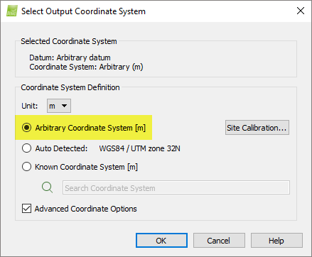
4. On the Select Output Coordinate System, select coordinate system Arbitrary Coordinate System and select as a unit either meters [m] or feet [ft].
5. Import the GCPs using the GCP/MTP Manager. The GCPs coordinate system must be in the same arbitrary coordinate system as the output coordinate system. For more information about how to import GCPs using the GCP/MTP Manager: How to import and mark ground control points (GCPs).
6. Mark the GCPs in the Basic Editor. For step-by-step instruction on how to mark the GCPs in the Basic Editor: How to import and mark ground control points (GCPs). The GCPs' marks can also be imported using an external file: Menu Project > GCP / MTP Manager... > GCP / MTP Table > Import / Export Marks....
7. When all GCPs are marked on the images, click Process > Reoptimize.
8. Click Process > Generate Quality Report, to generate the new Quality Report.
9. On the Menu bar, click Process > Quality Report... to open the Quality Report. At this stage of processing, the Geolocation Bias Translation corresponds to the mean Absolute Geolocation Error, which is usually large.
![]()
10. On the Menu bar, click Project > Select Output Coordinate System.
11. On the pop-up Select Output Coordinate System, under Coordinate System Definition, select Arbitrary Coordinate System.
12. On the pop-up Select Output Coordinate System, under Coordinate System Definition, select the checkbox Advanced Coordinate Options.
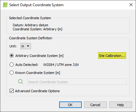
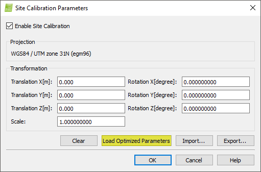
13. On the pop-up Select Output Coordinate System, in Arbitrary Coordinate System, click Site Calibration... The pop-up Site Calibration Parameters appears. It displays the transformation between the image and the GCP/output coordinate system as well as the coordinate systems between which the transformation is defined. Select the box Enable Site Calibration.
14. On the pop-up Site Calibration Parameters, click Load Optimized Parameters to load the transformation parameters estimated during processing.
14. In the window Site Calibration Parameters, click OK.
15. In the window Select Output Coordinate System, click OK.
The site calibration is loaded.
16. Verify visually if the site calibration is accurate.
16.1 From the menu bar, click View > Map View to display the Map View. Verify that the GCPs are displayed and located at the correct position.

16.2 On the Menu bar, click View > rayCloud to display the rayCloud. In the 3D View, verify that the initial image position is displayed (blue dot) and that it is close to the image computed position (green dot).

17. If the transformation is not accurate, verify that the GCPs initial coordinates and marks are correct. If they are not correct, correct them.
18. On the Menu bar, click Process > Reoptimize to apply the transformation to the project.
19. Click Process > Generate Quality Report, to generate the new Quality Report.
20. Verify that the transformation is good enough. In the Menu bar, click Process > Quality Report... to open the Quality Report. Check the table Absolute Geolocation Variance. The mean of the Geolocation Error in X,Y,Z should be close to 0 and the variance should be small. The Geolocation Coordinate System Transformation table displays the transformation as well as the geolocation bias.
![]()
21. Once the site calibration is good, export it for later use: On the Menu bar, click Project > Select Output Coordinate System.
22. On the pop-up Select Output Coordinate System, under Arbitrary Coordinate System, click Site Calibration...
23. On the pop-up Site Calibration Parameters, click Load Optimized Parameters to load the transformation estimated during processing. This transformation takes into account the transformation and geolocation bias displayed in the Quality Report.

![]()
24. On the pop-up Site Calibration Parameters, click Export... to export the transformation parameters to a file.
25. On the pop-up Site Calibration Parameters, click OK.
26. On the pop-up Select Output Coordinate System, click OK.