If the Camera Internals and Externals, AAT, BBA option is selected for step 1. Initial Processing under the Calibration tab (Menu Process > Processing Options... > 1. Initial Processing > Calibration), PIX4Dmapper generates a params folder.
This folder can be found in ...\project_name\1_initial\params.
The params folder contains the following files:
- dvp
- project_name_tp_bingo
- project_name_tp_orima
- project_name_tp_pix4d
- project_name_calibrated_camera_parameters
- project_name_calibrated_external_camera_parameters
- project_name_calibrated_external_camera_parameters_wgs84
- project_name_calibrated_external_camera_parameters error
- project_name_calibrated_images_position
- project_name_calibrated_internal_camera_parameters.cam
- project_name_pix4d_calibrated_internal_camera_parameters.cam
- project_name_ camera.ssk
- project_name_photo.ssk
- project_name_estimated_gcps_position (if GCPs have been imported to the project)
- project_name_image_to_output_transform
- project_name_measured_estimated_gcps_position (if GCPs have been imported to the project)
- project_name_measured_gcps_position (if GCPs have been imported to the project)
- project_name_pmatrix
- project_name_sun_angles
- project_name_offset.xyz
- project_name_wkt.prj
- project_name_result_correlations_internals
- project_name_point_uncertainties
dvp
It contains one file per image with the internal and external orientation and can be used in DAT/EM software. This file is only exported if the Undistorted Images option is selected in step 1. Initial Processing under the Calibration tab (Menu Process > Processing Options... > 1. Initial Processing > Calibration).
project_name_tp_bingo
It contains the image coordinates (for all calibrated images) for the GCPs and Check points and some of the Automatic Tie Points. These coordinates refer to the original (distorted) images. For more information: What is the bingo file generated during Initial Processing?. It can be used with the BINGO software.
project_name_tp_orima
It contains information for the calibrated cameras about the GCPs and Check points and some of the Automatic Tie Points. It can be used with the Orima software.
project_name_tp_pix4d
It contains the image coordinates (for all calibrated images) for the GCPs and Check points and some of the Automatic Tie Points. These coordinates refer to the original (distorted) images. The fourth column is the scale (relative accuracy) of the point. A point with scale 2 is more accurate than a point with scale 4. For example a point that was found on the edge of a building is probably more accurate than a point that was found on the textureless wall of a building.
project_name_calibrated_camera_parameters
For each calibrated camera, it contains the following information:
- fileName imageWidth imageHeight
- camera matrix K [3x3]
- radial distortion [3x1]
- tangential distortion [2x1]
- camera position t [3x1]
- camera rotation R [3x3]
- camera model m = K [R|-Rt] X = KRX - KRt = Pmatrix* X, where X is a 3D point.
project_name_calibrated_external_camera_parameters
For each calibrated camera, it contains the following information:
- image name
- X: The computed X coordinate in the output coordinate system.
- Y: The computed Y coordinate in the output coordinate system.
- Z: The computed Z coordinate in the output coordinate system.
- Omega: The computed Omega angle (degrees) in the output coordinate system. For more information How are omega, phi, kappa defined?.
- Phi: The computed Phi angle (degrees) in the output coordinate system. For more information How are omega, phi, kappa defined?.
- Kappa: The computed Kappa angle (degrees) in the output coordinate system. For more information How are omega, phi, kappa defined?.
For more information about the internal and external camera parameter definition: How are the Internal and External Camera Parameters defined?.
project_name_calibrated_external_camera_parameters_wgs84
For each calibrated camera, it contains the following information:
- image name
- longitude: The computed longitude in WGS84.
- latitude: The computed latitude in WGS84.
- altitude: The computed altitude in WGS84.
- Omega: The computed Omega angle (degrees) in the output coordinate system. For more information How are omega, phi, kappa defined?.
- Phi: The computed Phi angle (degrees) in the output coordinate system. For more information How are omega, phi, kappa defined?.
- Kappa: The computed Kappa angle (degrees) in the output coordinate system. For more information How are omega, phi, kappa defined?.
For more information about the internal and external camera parameter definition: How are the Internal and External Camera Parameters defined?.
project_name_calibrated_external_camera_parameters_error
For each calibrated camera, it contains the following information:
- imageName
- cameraIndex: Index to specify to which group the cameras belong to.
- cameraName
- X_opt: The computed X coordinate in the output coordinate system.
- Y_opt: The computed Y coordinate in the output coordinate system.
- Z_opt: The computed Z coordinate in the output coordinate system.
- X_gps: The input X position of the camera in the output coordinate system.
- Y_gps: The input Y position of the camera in the output coordinate system.
- Z_gps: The input Z position of the camera in the output coordinate system.
- X_acc: The X accuracy of the cameras position.
- Y_acc: The Y accuracy of the cameras position.
- Z_acc: The Z accuracy of the cameras position.
- Omega: The computed omega angle of the camera in degrees.
- Phi: The computed phi angle of the camera in degrees.
- Kappa: The computed kappa angle of the camera in degrees.
- Xo: The X position of the image row that is read out first, computed if the camera model is rolling shutter.
- Yo: The Y position of the image row that is read out first, computed if the camera model is rolling shutter.
- Zo: The Z position of the image row that is read out first, computed if the camera model is rolling shutter.
- Xrows: The X position of the image row that is read out last, computed if the camera model is rolling shutter.
- Yrows: The Y position of the image row that is read out last, computed if the camera model is rolling shutter.
- Zrows: The Z position of the image row that is read out last, computed if the camera model is rolling shutter.
- X_uncertainty: The uncertainty of the computed X coordinate in the output coordinate system.
- Y_uncertainty: The uncertainty of the computed Y coordinate in the output coordinate system.
- Z_uncertainty: The uncertainty of the computed Z coordinate in the output coordinate system.
- Omega_uncertainty: The uncertainty of the omega angle of the camera.
- Phi_uncertainty: The uncertainty of the phi angle of the camera.
- Kappa_uncertainty: The uncertainty of the kappa angle of the camera.
- X_rs_uncertainty: The uncertainty of the rolling shutter of the camera in the X dimension.
- Y_rs_uncertainty: The uncertainty of the rolling shutter of the camera in the Y dimension.
- Z_rs_uncertainty: The uncertainty of the rolling shutter of the camera in the Z dimension.
- inlierProb: Value between 0 and 1 indicating the outlier score (<0.5 corresponds to an outlier)
This information can be used to analyse the geolocation and accuracy of the input images positions.
For more information about the internal and external camera parameter definition: How are the Internal and External Camera Parameters defined?.
project_name_calibrated_images_position
For each calibrated camera, it contains the following information:
- image name
- X: The computed X coordinate in the output coordinate system.
- Y: The computed Y coordinate in the output coordinate system.
- Z: The computed Z coordinate in the output coordinate system.
For more information about the internal and external camera parameter definition: How are the Internal and External Camera Parameters defined?.
project_name_calibrated_internal_camera_parameters.cam
It contains the following information:
- FOCAL: Optimized (computed) focal length
- Principal Point Offset xpoff ypoff in mm (Inpho): The principal point offset in x and y direction as it should be used in the Inpho software. For more information: How to import PIX4Dmapper Outputs into Inpho.
- Principal Point Offset xpoff ypoff in mm: The principal point offset in x and y direction in mm.
- Principal Point Offset xpoff ypoff in pixel: The principal point offset in x and y direction in pixels.
- Information about the lens distortions.
project_name_pix4d_calibrated_internal_camera_parameters.cam
It contains information about the optimized (computed) internal camera parameters.
- Focal length in [mm]
- Principal point Py [mm]
- Principal point Py [mm]
- Symmetrical (Radial) Lens Distortion K1
- Symmetrical (Radial) Lens Distortion K2
- Symmetrical (Radial) Lens Distortion K3
- Tangential Lens Distortion T1
- Tangential Lens Distortion T2
For more information about the internal and external camera parameter definition: How are the Internal and External Camera Parameters defined?.
These internal camera parameters can also be found in the quality report. For more information: Quality report specifications.
project_name_ camera.ssk
It contains information about the camera parameters. It can be used with the ImageStation software or other compatible stereo viewing software.
project_name_photo.ssk
It contains information about the images. It can be used with the ImageStation software or other compatible stereo viewing software.
project_name_estimated_gcps_position
Generated if GCPs have been imported to the project. It contains the following information:
- GCP label
- X: The computed X coordinate in the output coordinate system.
- Y: The computed Y coordinate in the output coordinate system.
- Z: The computed Z coordinate in the output coordinate system.
project_name_image_to_output_transform
Defines the site calibration transformation between image geolocation coordinate system and output coordinate system. This file can be used in further projects by importing it in the Site Calibration Parameters window. For more information: How to use the Site Calibration Parameters.
project_name_measured_estimated_gcps_position
Generated if GCPs have been imported to the project. It contains the following information:
- GCP label
- GCP measured X: The input X coordinate given in the output coordinate system.
- GCP measured Y: The input Y coordinate given in the output coordinate system.
- GCP measured Z: The input Z coordinate given in the output coordinate system.
- GCP estimated X: The computed X coordinate in the output coordinate system.
- GCP estimated Y: The computed Y coordinate in the output coordinate system.
- GCP estimated Z: The computed Z coordinate in the output coordinate system.
- GCP weight: The weight that the GCP had for processing. The weight is based on the zoom level on which a GCP was marked. For more information: Menu Project > Basic GCP / MTP Editor > Preview
- GCP visible in # images: The number of images on which a GCP was marked.
project_name_measured_gcps_position
Generated if GCPs have been imported to the project. It contains the following information:
- GCP measured X: The input X coordinate given in the output coordinate system.
- GCP measured Y: The input Y coordinate given in the output coordinate system.
- GCP measured Z: The input Z coordinate given in the output coordinate system.
project_name_pmatrix
The P-Matrix contains information about the internal and external camera parameters. It allows to convert the 3D coordinates (X,Y,Z) of a 3D point into 2D coordinates (u,v) of an undistorted image. The 3D coordinates are expressed in the output coordinate system. An offset, located in the project_name_offset.xyz file, should be subtracted from the 3D coordinates before applying the P-Matrix.
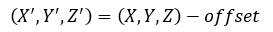
It can only be used with perspective lens cameras and with the undistorted images that are generated by PIX4Dmapper. (u,v) are the coordinates in the undistorted images given in pixels.
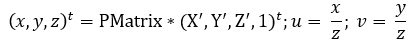
The first four numbers in the file correspond to the first row in the matrix.
project_name_sun_angles
It contains the angle of the irradiance sensor and the irradiance value when this information is available.
project_name_offset.xyz
It contains the offset between the centered points and the output coordinate system. It can be used for the textured mesh (.obj file) and densified points cloud (.ply and .xyz file). This is the difference between the local coordinate system in which some of the outputs are created and the output coordinate system.
project_name_wkt.prj
It contains the projection of the output coordinate system in the projection format.
project_name_result_correlations_internals
It contains the correlation values between the optimized internal camera parameters. The correlation is expressed from a range -1 to 1, i.e. 0 value is for parameters that are independent and 1 for parameters that are fully correlated. A negative correlation indicates that the one variable increases when the other decreases. It contains the following information:
- Camera model name.
- Camera model with distortions.
- Headers for columns - internal camera parameters: focal length, principal point Px, principal point Py, radial lens distortion R1, radial lens distortion R2, radial lens distortion R3, tangential lens distortion T1, tangential lens distortion T2.
- Correlation matrix.
project_name_point_uncertainties
It contains a reduced list of Automatic Tie Points (ATPs) with their calculated uncertainties. The uncertainties are calculated after the calibration step. This output is meaningful only in georeferenced projects. It contains the following information:
- Coordinates of the ATPs in the output coordinate system.
- Uncertainty values. The unit depends on the output coordinate system units.