- These instructions are part of the whole procedure on how to include Ground Control Points (GCPs) in the project. For more information about when to follow these instructions: How to include GCPs in the project.
- All GCPs must have the same coordinate system.
- GCPs can be marked in the rayCloud after step 1. Initial Processing has been completed.
1. Open the rayCloud: On the Menu bar, click View > rayCloud.
2. On the left sidebar, in the section Layers, click Tie Points, then click GCPs / MTPs. The list of GCPs is displayed:
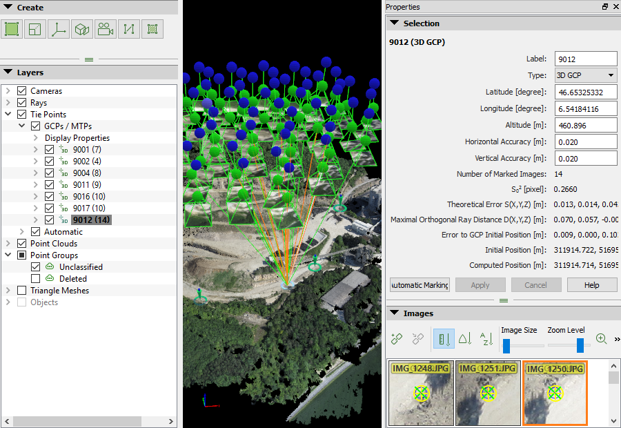
3. Select a GCP in the layer GCPs / MTPs: the right sidebar displays its properties and the list of images in which it is visible.
The estimated GCP position appears on the images with a blue circle with a dot in the middle. This position corresponds to the projection of the input 3D coordinates of that GCP in one particular image.
4. Navigate on the images to find the exact location of the GCP:
- Zoom in: Moving the mouse scroll wheel forwards.
- Zoom out: Moving the mouse scroll wheel backwards.
- Pan: Using the mouse left clicking.
- To change the size of the images: Move the thumb of Image Size bar.
- Spacebar: hover over an image with the mouse and hit the space in order to enlarge the image (full-screen mode).
5. Mark the exact position of the GCP on at least 2 images using the left mouse click.
- When marking a GCP on the images, all marks of this GCP are used to compute a new 3D point. At least 2 images need to be marked in order to compute the estimated 3D position of the GCP. This estimated 3D point is then reprojected in all the images where it might be visible in.
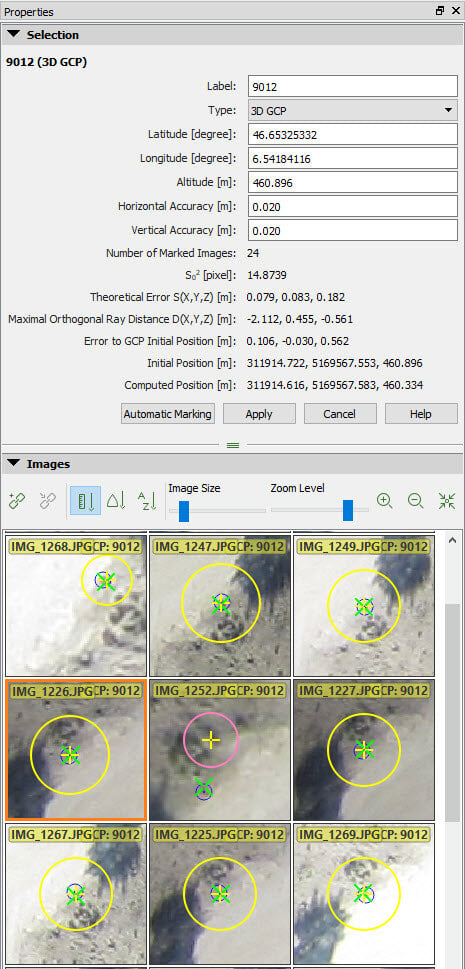
- The clicked position appears with a yellow cross and circle. The size of the yellow circle indicates the zoom level at which the marking has been done. Points that have been marked on a high zoom level are taken more into account than points that have been marked on a low zoom level.
- After marking a GCP on 2 images, a green cross appears on all images. The green cross represents the reprojection of the estimated 3D point and its location depends on the marks already made for the GCP.
- After marking a GCP on 2 images, a pink circle appears when the point is wrongly marked on other images. Outliers are indicated with pink circle and they do not influence the calibration results.
6. Click Automatic Marking: PIX4Dmapper will search for automatic color correlation of the clicked pixel on the rest of the images. Thereby, the position of the GCP will be optimized in more than the clicked images if the color correlation is good. The images that have a green and a yellow cross are taken into account during processing.
7. Check the rest of the images where no yellow cross appears:
- If the green cross indicates the correct GCP position: There is no need to mark the point on more images.
- If the green cross indicates the wrong GCP position: Mark the GCP on more images. Every time the GCP is marked on a new image, the green cross gets closer to the correct place.
8. When the green cross is at the correct position in most images, click Apply.
9. Repeat steps 3. to 8. for the rest of the GCPs.
10. When all GCPs are marked on the images, click Process > Reoptimize. This reoptimizes the reconstruction using the GCPs.
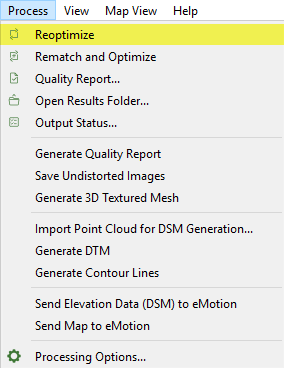
11. (optional) To Generate a new Quality Report, click Process > Generate Quality Report.