IN THIS ARTICLE
What are contour lines?
Generated with the digital surface model
Generated with the digital terrain model
During processing step 3. DSM, Orthomosaic and Index with the digital surface model
During processing step 3. DSM, Orthomosaic and Index with the digital terrain model
After processing step 3. DSM, Orthomosaic and Index
- Step 1. Initial processing should be processed and it is recommended that step 2. Point Cloud and Mesh is processed as well.
- The generation of contour lines is not included in any default processing template.
- Consider drawing a processing area at least before step 3. DSM, Orthomosaic and Index to restrict the area covered by contour lines.
What are contour lines?
Contour lines are lines connecting points of equal elevation. They give a better understanding of the variations in elevation of the land surface or topography of a project area.
Contour lines can be generated with the digital surface model (DSM) or the digital terrain model (DTM). The extent and highest resolution possible of the contour lines will depend on the source layer.
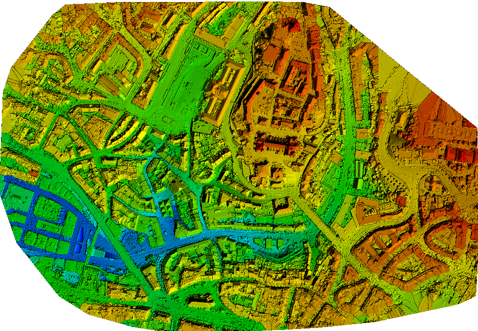
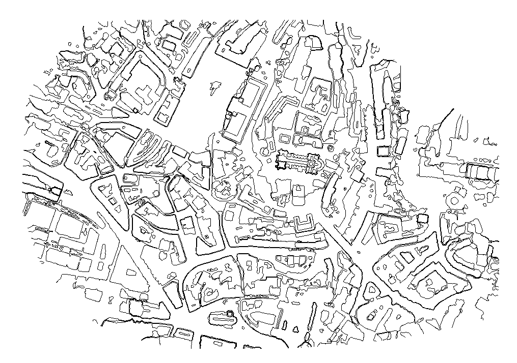
Generated with the digital surface model
Generating contour lines with the digital surface model (DSM) is recommended when there are no objects on the project's surface, such as high vegetation or buildings.
You can achieve a high level of detail in the contour lines because the DSM can have a resolution as high as the average ground sampling distance (GSD) of the project.
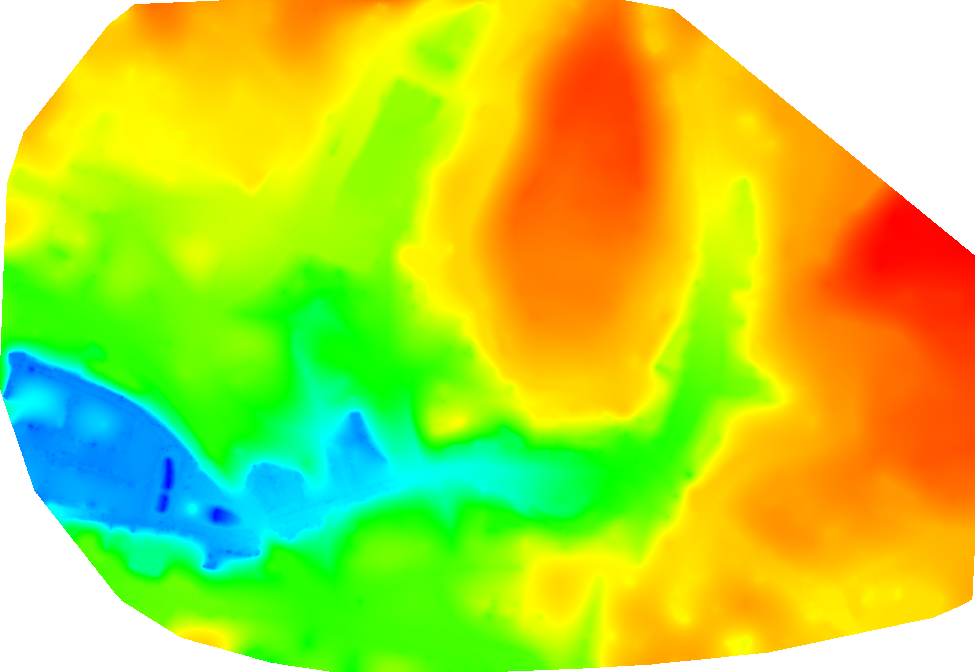
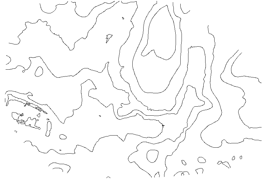
Generated with the digital terrain model
Generating contour lines with the digital surface model (DTM) is recommended when there are objects on the project's surface, such as high vegetation or buildings.
You can achieve a moderate level of detail in the contour lines because the DTM can have a resolution as high as five times the average ground sampling distance (GSD) of the project.
- Under project_name_interval_resolution_minimum_line_size_DSM if the contour lines are generated with the DSM.
- Under project_name_interval_resolution_minimum_line_size_DTM if the contour lines are generated with the DTM.
- As a consequence, contour lines generated with the same source layer and with the same options will be automatically overwritten.
During processing step 3. DSM, Orthomosaic and Index with the digital surface model
- On the menu bar, click Process > Processing Options...
- Click 3. DSM, Orthomosaic and Index.
- Select the tab DSM and Orthomosaic.
- In the section Raster DSM, make sure that GeoTIFF and Merge Tiles are selected.
- Select the tab Additional Outputs.
- In the section Contour Lines, check the box next to the desired output format(s).
- If necessary, change the Elevation Interval [unit], Resolution [cm] and Minimum Line Size [vertices] values. For more information about the contour lines options: Menu Process > Processing Options... > 3. DSM, Orthomosaic and Index > Additional Outputs.
- Click OK.
- On the menu bar, click View > Processing.
- Check the box next to 3. DSM, Orthomosaic and Index.
- Click Start.
During processing step 3. DSM, Orthomosaic and Index with the digital terrain model
- On the menu bar, click Process > Processing Options...
- Click 3. DSM, Orthomosaic and Index.
- Select the tab DSM and Orthomosaic.
- In the section Raster DSM, make sure that GeoTIFF and Merge Tiles are selected.
- Select the tab Additional Outputs.
- In the section Raster DTM, select GeoTIFF and Merge Tiles.
- In the section Contour Lines, check the box next to the desired output format(s).
- If necessary, change the Elevation Interval [unit], Resolution [cm] and Minimum Line Size [vertices] values. For more information about the contour lines options: Menu Process > Processing Options... > 3. DSM, Orthomosaic and Index > Additional Outputs.
- Click OK.
- On the menu bar, click View > Processing.
- Check the box next to 3. DSM, Orthomosaic and Index.
- Click Start.
After processing step 3. DSM, Orthomosaic and Index
- Step 3. DSM, Orthomosaic and Index must be processed.
- The digital surface model (DSM) has to have been exported in the GeoTIFF format and the tiles merged.
- On the menu bar, click Process > Processing Options.
- Click 3. DSM, orthomosaic and Index.
- Click the tab Additional outputs.
- Under the section Contour Lines, check the box next to one or several file formats.
Tip: At first, you can consider generating contour lines in the PDF format only in order to visualize the results quickly. Then, generate the contour lines in the final format(s) when you are pleased with the results. Generating contour lines in the PDF format is relatively fast.
- [if necessary] Under the section Contour Lines, select values for Elevation Interval [m], Resolution, and Minimum Line Size [vertices].
- On the menu bar, click Process > Generate contour lines (DSM) or click Process > Generate contour lines (DTM).
Access: The digital terrain model (DTM) has to have been exported in the GeoTIFF format and the tiles merged.