IMAGINE photogrammetry (formerly LPS) software is tightly integrated into the ERDAS IMAGINE ribbon interface. It is possible to use Pix4Dmapper outputs (camera parameters and optimized position) into IMAGINE Photogrammetry following these steps:
1. Process step 1. Initial Processing.
2. Open the files ( located in /projectname/1_initial/params ):
- projectname_calibrated_external_camera_parameters.txt
- projectname_calibrated_internal_camera_parameters.cam
3. Calculate the average flying height, Pixel size in x direction and Pixel size in y direction as follows:
- The average flying height is the distance between the camera at the shooting time and the average ground elevation.
Average flying height= average image Height- average ground elevation - Pixel size in x direction= (sensor width x1000)/image width(micrometers).
- Pixel size in y direction=(sensor height x1000)/image height(micrometers).
- Usually Pixel size in x direction = Pixel size in y direction.
- Average flying height = 3633 - 3033 = 600m
- Pixel size in x direction = (22.3012000 x 1000) / 4272 = 5.22
- Pixel size in y direction = (14.8675x 1000) / 2848 = 5.22
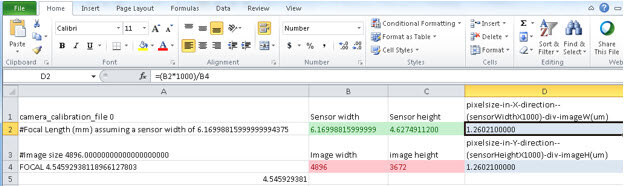
4. Adjust the files in order to be compatible with IMAGINE by creating an excel file like in the following picture:

5. . From the ERDAS IMAGINE interface click FILE | NEW | Photogrammetric Project which will open the Create New Block File (project) window:
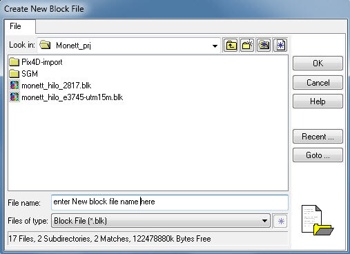
6. Navigate to a folder with written permission. Next to File name enter the name of the block file and click OK.
7. This will open the Model Setup where a geometric model that corresponds to the type of camera associated with the images can be selected. Click Digital Camera in the Geometric Model list.
8. Click OK to close the Model Setup dialog box.
9. The Block Property Setup dialog box opens.
10. Click Set in the Horizontal Reference Coordinate System section to select the proper coordinate system from the Quality Report file generated by Pix4Dmapper. UTM seems to work the best as it is Cartesian. The UTM EPSG zone can be located from a simple internet search and importing it into the Projection Chooser, it will auto-define the rest of the specifics associated with EPSG zone.
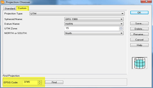
11. If the EPSG zone is not known, click the Standard tab in the Projection Chooser dialog.
12.Click the Categories dropdown list and the coordinate system. In this project: UTM Zone 15 GRS 1980 NAD83 North (which is EPSG code 3745).
13. Click OK to close the Projection Chooser dialog box.
14. After clicking OK, ensure that the Horizontal Units are correct in the block property setup dialog (Meters in this project).
15. Click Next in the Block Property Setup dialog. The Set Frame-Specific Information section displays:
16. Enter the value of the Average Flying Height (meters) as calculated above, then press Enter.
The flying height can also be calculated by multiplying the focal length by the image scale. An average flying height must be supplied before clicking Enter.
17. Click OK to close the Block Property Setup dialog box.
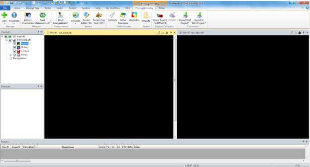
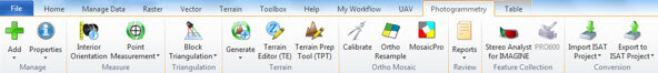
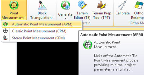
18. The Ribbon Interface is displayed:
19. Click the Add Images icon (upper left corner) to add images to the project. The Image File Name dialog opens:
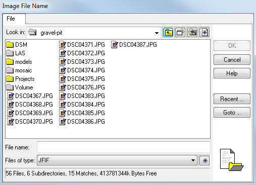
20. Navigate the folder, select the first file.
21. Hold down the Shift key and select the last file in the list.
22. Click OK to close the Image File Name dialog. If the PYR Attribute column at the bottom is not green, compute pyramid layers. To do this, simply click on any of the red PYR boxes in the attribute table. The Compute Pyramid Layers dialog opens:
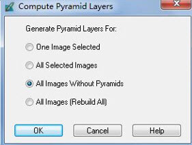
23. In the Compute Pyramid Layers dialog, confirm that the All Images Without Pyramids radio button is selected. Click OK in the Compute Pyramid Layers dialog.
24. Select the Interior Orientation icon on the top toolbar, the Digital Camera Frame Editor dialog opens:
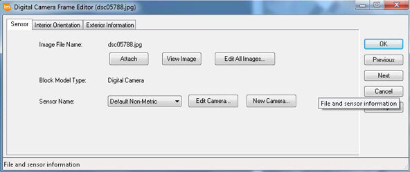
25 In the Sensor Name section, click the New Camera button. The Camera Information dialog opens:
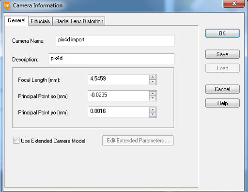
26. Enter the camera model in the Camera Name text field.
27. Enter Focal Length (mm) that can be found in the Pix4Dmapper camera parameters.
28. Enter the Principal Point x0 (mm) that can be found in the Pix4Dmapper camera parameters.
29. Enter the Principal Point y0(mm) that can be found in the Pix4Dmapper camera parameters.
30. Click OK to close the Camera Information dialog.
31. Click the Interior Orientation tab in the Digital Camera Frame Editor dialog.
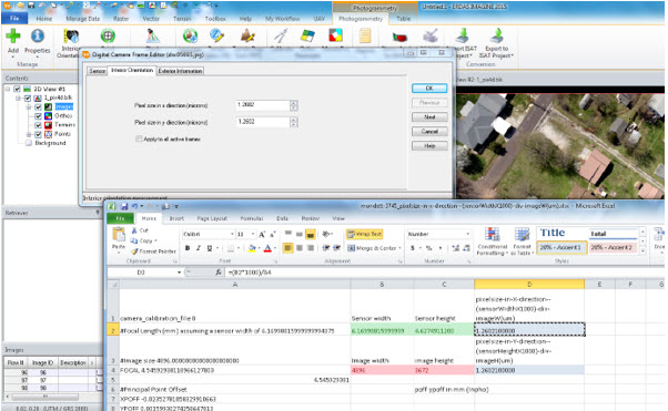
32. Enter the Pixel size in x direction (micrometers) as calculated before.
33. Enter the Pixel size in y direction (micrometers) as calculated before.
34. Check the Apply to all active frames box.
35. Click the Exterior Information tab in the Frame Camera Frame Editor dialog.
36. Click the Edit All Images tab in the Frame Camera Frame Editor dialog. The Fiducial Orientation and Exterior Orientation Parameter Editor opens:
37. Copy the Exterior Information from the excel file previously created (step 4). Click X0 and drag the mouse to Kappa. Click the Kappa dropdown list, select Edit and click Paste
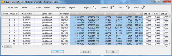
38. Click OK to close the Fiducial Orientation and Exterior Orientation Parameter Editor.
39. Confirm that the Set Status is set to Fixed.
40. Check the Apply status to all active frames checkbox.
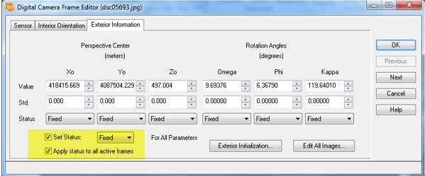
41. Click OK to close Digital Camera Frame Editor dialog box.
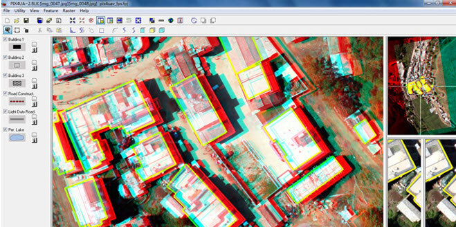
After completing the interior orientation process, the images in the block file overview are displayed as above. This project can be used for DEM Extraction, stereo viewing, 3D feature collection and generate Digital Line Graph (DLG).
Perform Auto-Tie point collection
This will tighten up the solution and make auto locating any control points much easier and more precise.
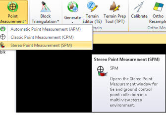
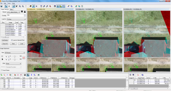
Stereo Control Point Measurement
Once the project has a tight solution, the SPM interface can be used to collect control with automated drive to features and auto location of the points, especially when they overlap so many UAV images. Refinement in a stereo environment makes for less ground work.
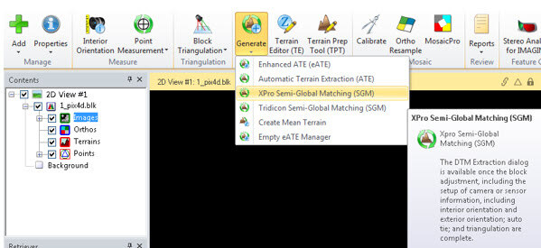
Generate and Edit DSM, TIN and SGM Point Clouds
Many different elevation extraction options exist from sparse Surface models to more dense SGM Point Cloud options. From the main IMAGINE Photogrammetry toolbar, under the Generate icon, one of the terrain extraction options can be selected.
In many mapping projects, terrain breaklines are needed to ensure contours represent the terrain as accurately as required. This can also be done in IMAGINE Photogrammetry Terrain Editor as well as ERDAS Terrain Editor for ArcGIS.
Stereo viewing and 3D feature collection
It is possible to perform 3D feature collection from this Stereo imagery blk Project. Feature collection can be done in Stereo Analyst for IMAGINE (SAFI) or even from Stereo Analyst for ArcGIS and the interface will look similar to that shown below (SAFI):
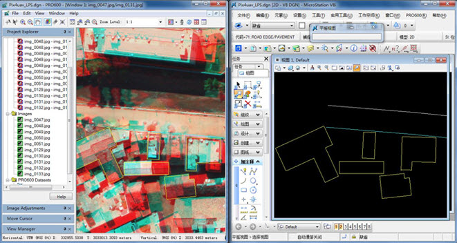
Digital Line Graph (DLG)
Dynamic linking to Pro600 in the Microstation environment allows for viewing and editing for your DLG’s. The synced interface will look similar to that shown below:
Disclaimer: Pix4D publishes this information as a courtesy to its customers. Pix4D makes no warranty of any kind, expressed or implied, with respect to the content's validity or accuracy.