Access: On the Menu bar, click
View > rayCloud to open the
rayCloud. The sidebar is displayed on the right of the Main window after these actions:
- For points (Automatic or Manual Tie Points or GCPs):
- When clicking a point in the rayCloud or selecting it in the Layers section.
- When double clicking a point in the image preview of the Selection section of the right sidebar.
- For objects (Polylines, Surfaces, Scale Constraints, Orientation Constraints): When clicking an object in the rayCloud or selecting it in the Layers section.
The Images section contains the following buttons:
-
 New Tie Point: Enabled for points (Automatic or Manual Tie Points or GCPs), not enabled for objects (polylines, surfaces, scale constraints, orientation constraints). Allows the user to create a new Manual Tie Point, 2D/3D GCP and/or a Check Point.
 -
 Connect to Tie Point: Only enabled for uncalibrated cameras. Used for manually calibrating cameras: How to manually calibrate uncalibrated Cameras in the rayCloud.
 -
 Sort Images by Distance: Sort the images by distance to the selected point / object, from the closest to the furthest. Images with marked points are displayed first.
 -
 Sort Images by Reprojection Error: Sort the images by reprojection error, from the highest to the lowest error. Images with marked points are displayed first. For more information: Reprojection error.
 -
 Sort Images by Name: Sort the images by name using alphabetical order.
 - Image Size slider: Allows to change the size of the images displayed in the Images section.
- Zoom Level slider: Allows to change the zoom level for the images displayed in the Images section.
-
 Zoom In All Images: Zooms in all the images displayed in the Images section.
 -
 Zoom Out All Images: Zooms out all the images displayed in the Images section.
 -
 Focus on Selection: Centers and zooms to the selected point / object.
Tip: For the selected image:
- In order to zoom in/out: Place the mouse over the location on which to zoom and move the mouse scroll button forwards/backwards.
- In order to pan: Place the mouse over the location on which to pan, and press the left button while dragging the mouse.
- By placing the mouse over an image and typing space, the image is displayed in full screen, where it is possible to zoom, pan, click, etc.
- When using the full screen mode, by typing:
- Space: It minimizes the image and keeps the full screen zoom and panning level.
- Esc: It minimizes the image and keeps the previous zoom and panning.
Different elements are displayed on the images depending on the object / point that is selected.
For Objects
- Green cross: Reprojection of the 3D vertex in the 2D images.
- Green line: Lines between the vertices of the objects.
- Yellow cross: (optional) Position where the selected vertex has been marked.
Note: A
Manual Tie Point is associated to each vertex of the object.
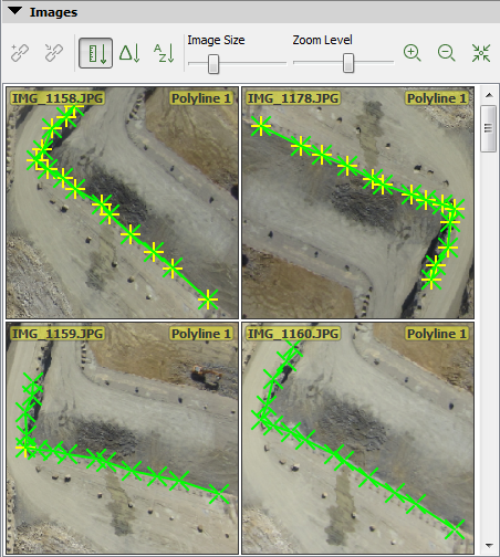
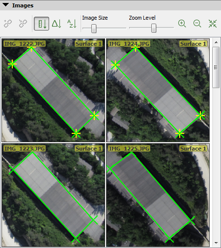
Polyline Object
Surface Object
Figure 1. Different Objects in the Images section.
For Points
- Automatic Tie Points:
- Green cross: Reprojection of the 3D point on the 2D image.
- Orange cross: Position where the associated 2D keypoints have automatically been detected.
- Orange circle: The radius of the orange circle indicates the size of the area that has been taken into account in order to detect the keypoint.
- Manual Tie Points / GCPs:
- Green cross: Projection of the 3D point computed from marks of the selected Manual Tie Point or GCP.
- Yellow cross: Position where the selected Manual Tie Point or GCP has been marked.
- Yellow circle: Its radius indicates the zoom level at which the selected Manual Tie Point or GCP has been marked. It defines the area in which the point has to be reprojected when estimating the 3D position. The higher the zoom level, the more influence the mark has on the reconstruction.
- Blue circle: The position corresponds to the projection of the input 3D coordinate of the selected GCP / Check Point.
- Non-matched automatic keypoints: Selected when double clicking on a red cross in the Image Preview of the Selection section in the Image View Sidebar for an uncalibrated camera.
- Green cross: The currently selected keypoint could potentially be matched to a group of keypoints already matched together. A 3D point is associated to this group of keypoints. The green cross represents the projection of this 3D point.
- Orange cross: The currently selected keypoint could potentially be matched to a group of keypoints already matched together. The orange cross represents the position where the keypoints of this group have been automatically detected.
- Orange circle: The currently selected keypoint could potentially be matched to a group of keypoints already matched together. The radius of the orange circle indicates the size of the area that has been taken into account in order to detect this keypoint.
- Potentially matched automatic keypoints: Selected when double clicking on an orange cross in the Image Preview of the Selection section of the right sidebar for an uncalibrated camera.
- Green cross: The currently selected keypoint has a high probability of being matched to a group of keypoints already matched together. A 3D point is associated to this group of keypoints. The green cross represents the projection of this 3D point.
- Orange cross: The currently selected keypoint has a high probability of being matched to a group of keypoints already matched together. A 3D point is associated to this group of keypoints.
- Orange circle: The currently selected keypoint has a high probability of being matched to a group of keypoints already matched together. The radius of the orange circle indicates the size of the area that has been taken into account in order to detect this keypoint.
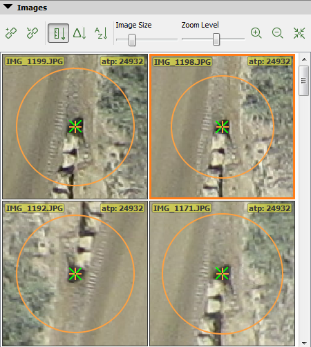
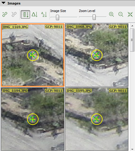
Automatic Tie Point
Marked GCP / Check point
Figure 2. Green, orange, yellow and blue crosses in the
Images section
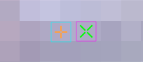
Note: The selected point / vertex of an object can be marked on the images by clicking the point on the images:
- Pan the image: Left click and move the mouse.
- Marking a point: Click on the image location where the point is visible to mark it.
- Modifying a point: Hover over the existing green or yellow cross. The mouse cursor becomes a cross with arrows. Left click and move the mouse to the new position.
- Deleting a mark: Hover over the image in which the point has already been marked and click Delete.
Note: When zooming in on the images, after a given zoom level, a light blue or purple square centered on the cross are displayed. This square indicates the size of one pixel.