- Images: On the Menu bar, click Project > Image Properties Editor..., on Coordinate System, click Edit...
- GCPs: On the Menu bar, click Project > GCP/MTP Manager..., on GCP Coordinate System, click on Edit...
- Outputs:
- On the Menu bar, click Project > Select Output Coordinate System...
- When creating a new project, after defining the Processing Options Template, the Select Output Coordinate System window is displayed.
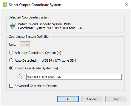
There are 2 sections:
- Selected Coordinate System: Section that displays the currently selected coordinate system.
- Coordinate System Definition: Section that allows to select the coordinate system.
And 3 buttons:
- OK: Confirms and applies the changes.
- Cancel: Does not save the changes and exits the pop-up.
- Help: Opens the PIX4Dmapper help.
Selected Coordinate System
This section displays the currently selected coordinate system:
- Datum: Represents the selected datum.
- Coordinate System: Represents the selected 2D coordinate system.
Based on the selected datum and coordinate system the following icons appear:
 When the selected coordinate system is WGS 84.
 When the selected coordinate system is any Coordinate System other than WGS 84.
- For the images: WGS84 (egm96). If the images are captured with a senseFly drone, the default Selected Coordinate System is WGS 84 (Geoid HeightAbove WGS 84 Ellipsoid=0).
- For the GCPs: The coordinate system that is selected when creating a new project under the Output / GCP Coordinate System section: Step 2. Creating a Project.
- For the Outputs:
- Arbitrary: if the project has neither image geolocation nor GCPs.
- The corresponding UTM zone: if the project has image geolocation.
- The coordinate system that is selected for the GCPs: if the project has GCPs.
Coordinate System Definition
There are the following options:
- Unit: It is used to set the unit of the coordinate system. The unit can be meter (m) or international foot (ft).
- Arbitrary Coordinate System [unit]: It is used for coordinate systems that the origin, the scale and the orientation are defined by the user.
- Auto detected (only for the Output Coordinate System): Based on the coordinates of the images and the selected unit, PIX4Dmapper auto detects a coordinate system. If the project does not have image geolocation, this option is not available.
- Known Coordinate System [unit]: It is used to select a known coordinate system. The search text box allows to find the coordinate system in auto-complete mode from PIX4Dmapper's database.
- Advanced Options: By enabling this check box, depending the selected coordinate system (Image, GCP or Output), some buttons or sections are displayed, for:
- Arbitrary Coordinate System
- Auto detected
- Known Coordinate System
Advanced Options

Opens the Site Calibration Parameters pop-up:
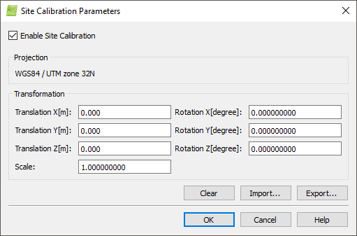
The Site Calibration Parameters window has 2 sections:
- Projection: Defines the known coordinate system involved in the transformation.
- Transformation: Defines the transformation between the known coordinate system (the one of the images or a user defined system) and an arbitrary output coordinate system. The transformation consists in a translation, rotation and scaling with respect to the output coordinate system. The Site Calibration Parameters window contains the following fields:
- Translation X [unit]: Translation along the X axis.
- Translation Y [unit]: Translation along the Y axis.
- Translation Z [unit]: Translation along the Z axis.
- Rotation X [degree]: Rotation around the X axis.
- Rotation Y [degree]: Rotation around the Y axis.
- Rotation Z [degree]: Rotation around the Z axis.
- Scale: Scaling between the two systems.
The Site Calibration Parameters window contains the following buttons:
- Clear: Clears the transformation parameters.
- Load Optimized: Loads the optimized transformation parameters that are displayed in the Quality Report. This option is available only if the project has GCPs.
- Import...: Imports the transformation parameters from file. This file can contain the user defined known coordinate system
- Export...: Exports the transformation parameters to file.
- OK: Confirms the changes.
- Cancel: Does not save the changes and exits the pop-up.
- Help: Opens the PIX4Dmapper help.
It defines the vertical coordinate system.
There are the following options:
- MSL:
- egm84: When the altitudes are based on the EGM84 geoid. The approximate EGM84 geoid height above WGS84 is displayed.
- egm96: When the altitudes are based on the EGM96 geoid. The approximate EGM96 geoid height above WGS84 is displayed.
- egm2008: When the altitudes are based on the EGM08 geoid. The approximate EGM08 geoid height above WGS84 is displayed.
- Geoid Height Above WGS84 Ellipsoid [unit]: When the altitudes are based on a geoid other than EGM84, EGM96, EGM08. The user can set the difference between the geoid and the WGS84 ellipsoid. If the altitudes are based on the WGS84 ellipsoid, then the Geoid Height Above WGS84 Ellipsoid is 0.000 (zero).
- Arbitrary: When the reference of the altitudes is unknown, user defined or the ground (Above Ground Level altitudes). When this option is selected, no altitude conversion is performed.
It is used to define the coordinate system.
- The .prj file contains information that defines the coordinate system. For more information about the Coordinate system file: Input files.
- Select this option to import an existing .prj file. For more information about how to obtain or create a .prj coordinate system file: How to obtain or create a .prj coordinate system syntax file.
Opens the Import .prj File pop-up, with the following options:
- On File name it is displayed the selected .prj file.
- Open: Opens the selected folder.
- Cancel: Does not save the changes and exits the pop-up.
It is used to select a known coordinate system from PIX4Dmapper's database.
Opens the Coordinate System pop-up:

The Select Coordinate System section has 2 drop-down lists:
- On Datum, by clicking on the arrow, a drop-down list appears that allows to select among different datum.
- On Coordinate System, by clicking on the arrow, a drop-down list appears that allows to select among different coordinate systems.
And 3 buttons:
- OK: Confirms the changes.
- Cancel: Does not save the changes and exits the pop-up.
- Help: Opens the PIX4Dmapper help.
The EPSG Geodetic Parameter Dataset is a widely used database of Earth Ellipsoids, geodetic datums, geographic and projected coordinate systems, units of measurements, etc.
It is used to select a known coordinate system from an EPSG code.
Opens the Coordinate System pop-up:
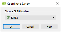
On the Choose EPSG Number section, by clicking on the arrow, a drop-down list appears that allows to select among different EPSG codes.
There are 3 buttons:
- OK: Confirms the changes.
- Cancel: Does not save the changes and exits the pop-up.
- Help: Opens the PIX4Dmapper help.