This article explains each piece of information about the Ground Control Points (GCPs) and Manual Tie Points (MTPs). The information on the GCPs and MTPs can be viewed at the sidebar on the right when using the rayCloud.
Access: On the Menu bar, click View > rayCloud to open the rayCloud. The right sidebar is displayed on the right of the main window.
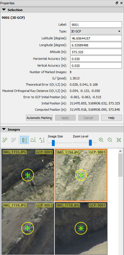
- The GCP or Manual Tie Point information is displayed when selecting a given 2D GCP, 3D GCP, Check point or Manual Tie Point in the 3D View or in the Layers section of the left sidebar.
The following information is displayed:
- Label: The name of the point.
- Type: The type of the point (3D GCP, 2D GCP, Check point, Manual Tie Point).
- First Coordinate:
- Latitude [degree]: If the coordinate system of the GCPs is a geographic coordinate system.
- X [m]: If the coordinate system of the GCPs is a projected coordinate system. The unit is given in meters.
- X [feet]: If the coordinate system of the GCPs is a projected coordinate system. The unit is given in feet.
- Arbitrary X [m]: If the coordinate system of the GCPs is defined by the user (local coordinate system). The unit is given in meters.
- Arbitrary X [feet]: If the coordinate system of the GCPs is defined by the user (local coordinate system). The unit is given in feet.
- Second Coordinate:
- Longitude [degree]: If the coordinate system of the GCPs is a geographic coordinate system.
- Y [m]: If the coordinate system of the GCPs is a projected coordinate system. The unit is given in meters.
- Y [feet]: If the coordinate system of the GCPs is a projected coordinate system. The unit is given in feet.
- Arbitrary Y [m]: If the coordinate system of the GCPs is defined by the user (local coordinate system). The unit is given in meters.
- Arbitrary Y [feet]: If the coordinate system of the GCPs is defined by the user (local coordinate system). The unit is given in feet.
- Third coordinate:
- Altitude [m]: If the coordinate system of the GCPs is a geographic coordinate system.
- Z [m]: If the coordinate system of the GCPs is a projected coordinate system. The unit is given in meters.
- Z [feet]: If the coordinate system of the GCPs is a projected coordinate system. The unit is given in feet.
- Arbitrary Z [m]: If the coordinate system of the GCPs is defined by the user (local coordinate system). The unit is given in meters.
- Arbitrary Z [feet]: If the coordinate system of the GCPs is defined by the user (local coordinate system). The unit is given in feet.
- Horizontal Accuracy [units]: The horizontal accuracy is defined for the 2D and 3D GCPs. For more information: GCP / Manual Tie Point Table - PIX4Dmapper
- Vertical Accuracy [units]: The vertical accuracy is defined for the 3D GCPs. For more information: GCP / Manual Tie Point Table - PIX4Dmapper
- Marks in images: The number of images on which the point is marked.
- Sο2 [pixel]: A posteriori variance component of all the marked points for a given 3D point. For more information: 3D error estimation from tie points.
- Theoretical Error S(X,Y,Z) [units]: Theoretical error estimation. For more information: What is the difference between theoretical error and the error to GCP initial position? - PIX4Dmapper
- Maximal Orthogonal Ray Distance D (x,y,z)[units]: Maximal distance from the estimated 3D point and all the rays used to compute that 3D point. The distance is measured between the 3D point and the point defined by the line perpendicular to the ray passing through the 3D point.
- Error to GCP Initial Position [units]: Error in X, Y, Z between the original 3D position and the estimated 3D position. This information does not appear for Manual Tie Points.
- Initial Position [units]: The initial X, Y, Z position of the 3D GCP, Manual Tie Point or Check point. The initial X, Y position of the 2D GCP.
- Computed Position [units]: The computed X, Y, Z position of the 3D GCP, Manual Tie Point or Check point. The computed X, Y position of the 2D GCP.
Below the table there are four buttons:
- Automatic Marking: Allows the user to automatically mark the 3D point in the images that have not been marked. This button is activated when the 3D point has been marked in at least two images.
- Apply: This button is active when the image marks have been modified, i.e. when a new image has been marked or when an existing mark has been updated or removed. When clicking this button, the new marks are taken into account and the 3D position of the corresponding point is recomputed. This button is also active when a change is done in the information regarding the point.
- Cancel: Changes made to the marks of the point in the images or the information of the point will not be saved when this button is clicked.
- Help: Opens the PIX4Dmapper help.
The Images section: Displays the selected image and the other images where the point can be found. For more information: Menu View > rayCloud > Right sidebar > Images section.
Important: The zoom level at which GCPs / Manual Tie Points are marked has an impact on the GCP / Manual Tie Point error obtained in the Quality Report. Usually, the higher the zoom level, the more precisely the GCP / Manual Tie Point is marked. These GCPs / Manual Tie Points will have a bigger impact on the reconstructed model than GCPs / Manual Tie Points marked on a lower zoom level; lower error values are also expected for these GCPs / Manual Tie Points. For example, when GCPs / Manual Tie Points are marked without zooming into the images, the GCP / Manual Tie Point error can be 10 times higher than when the GCPs / Manual Tie Points are marked by zooming into the images.