In PIX4Dmapper, the menu bar displays the following options:
- Viewpoint
- Navigation Modes
- Perspective/Orthographic
- Change Background...
- Display Sky
- New Processing Area
- New Scale Constraint
- New Orientation Constraint
- New Orthoplane
- New Video Animation Trajectory...
- New Polyline
- New Surface
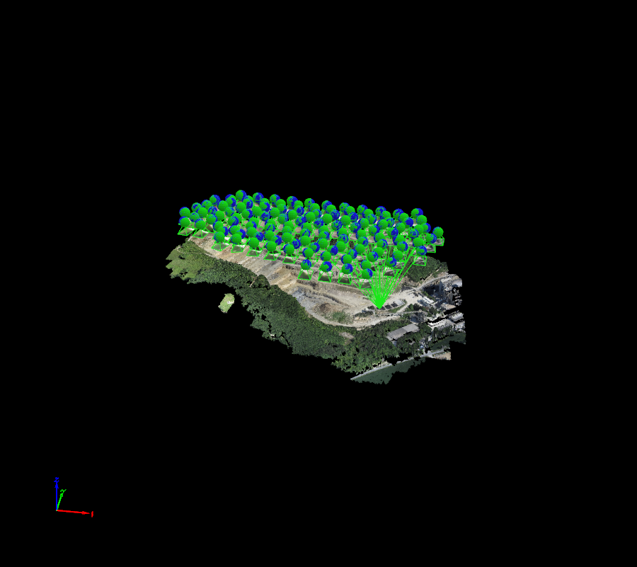
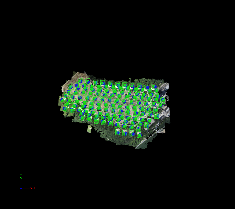
Allows to select pre-defined viewpoints for the 3D View. These predefined viewpoints are accessible:
- Using the Menu bar rayCloud > Viewpoint or the Menu bar Volumes > Viewpoint.
- Using the keyboard.
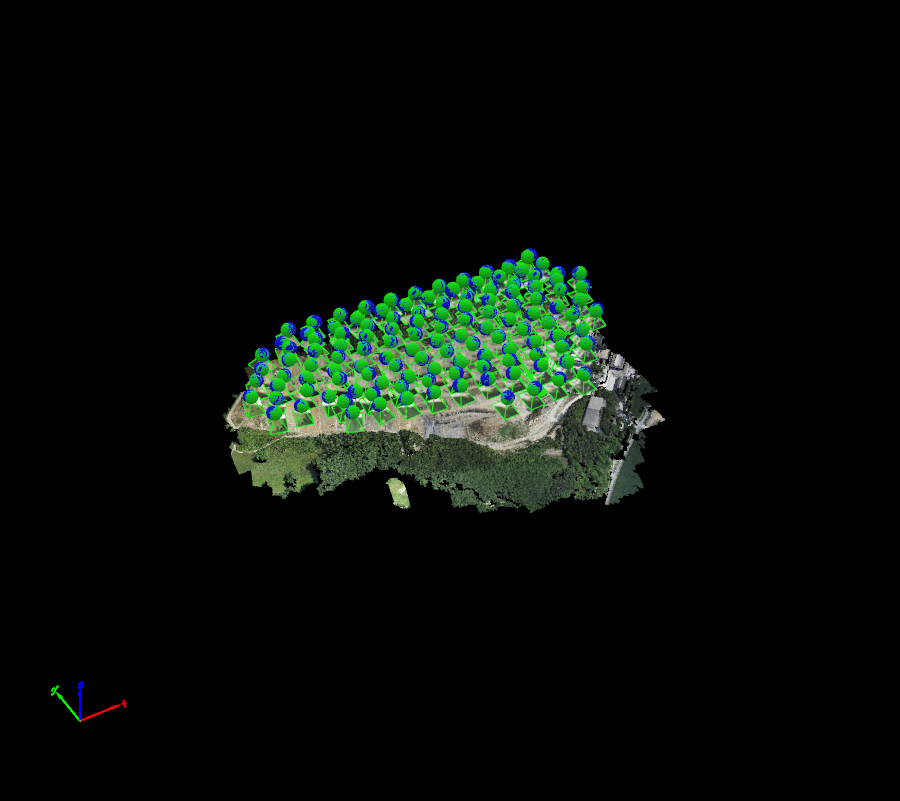
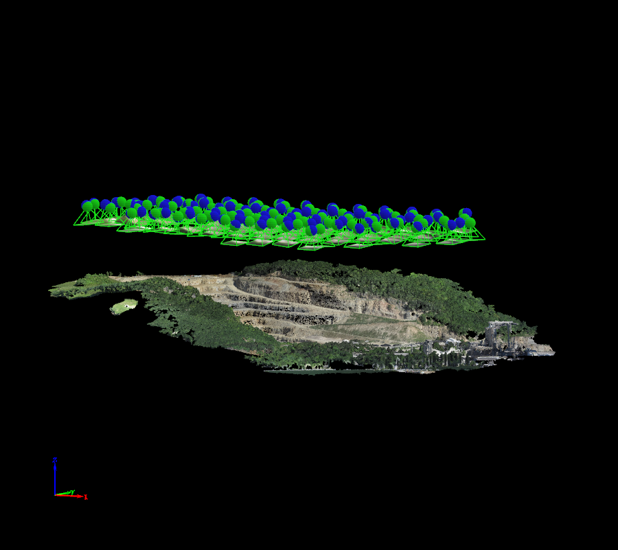
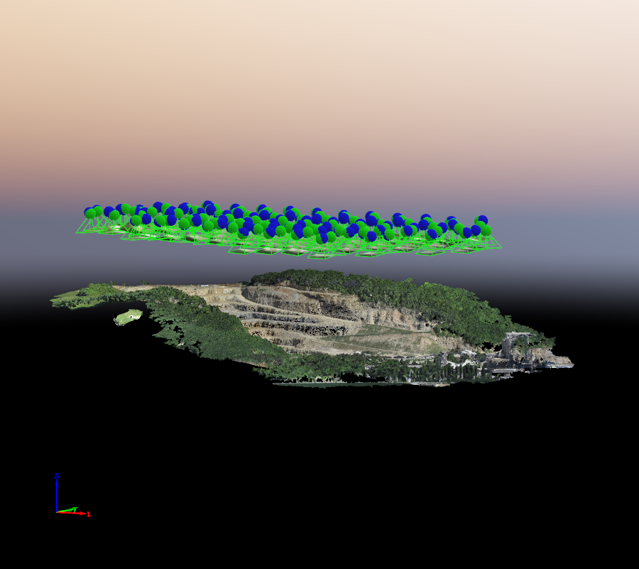
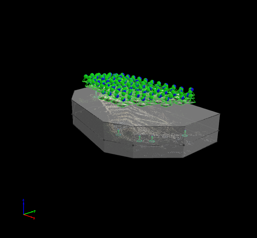
- View All: Moves the viewpoint in order to fit all the layers in the 3D View.
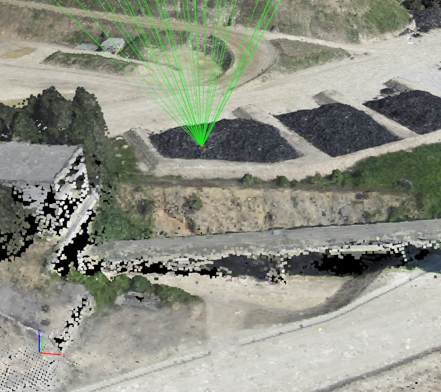
- Focus on Selection: Moves the viewpoint in order to display in detail the selected element (point, camera).
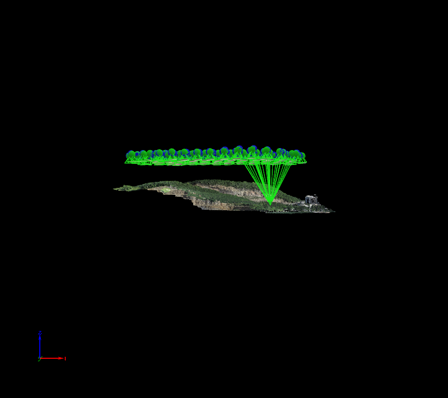
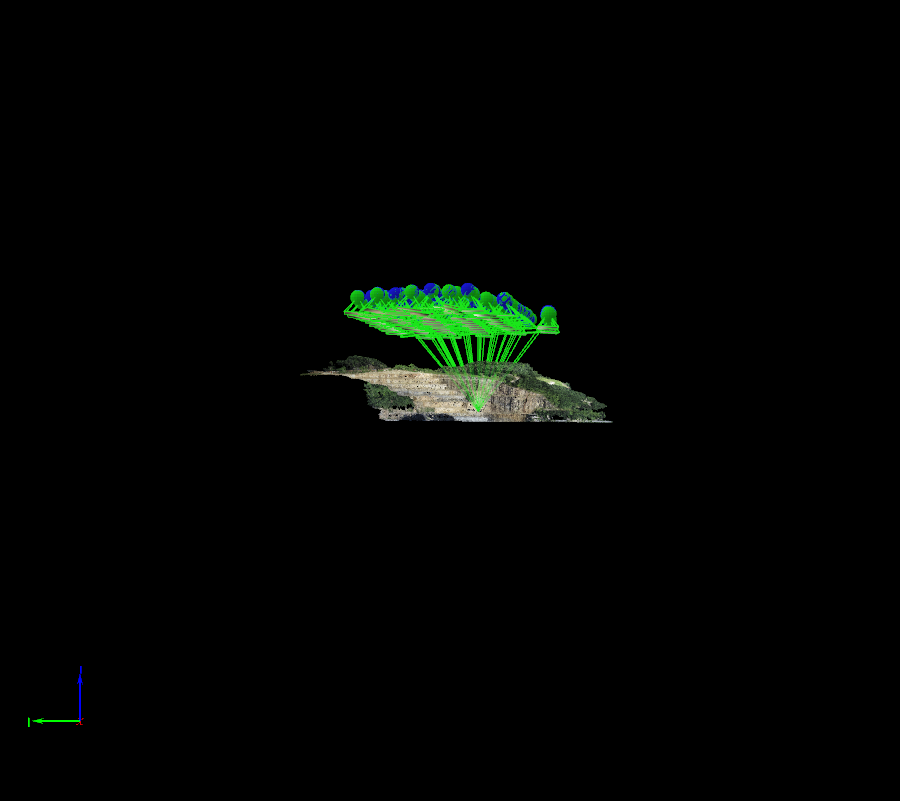
- Top: Moves the viewpoint in such a way that the layers are viewed from the top and fits all the layers in the 3D View.
- Front: Moves the viewpoint in such a way that the layers are viewed from the front and fits all the layers in the 3D View.
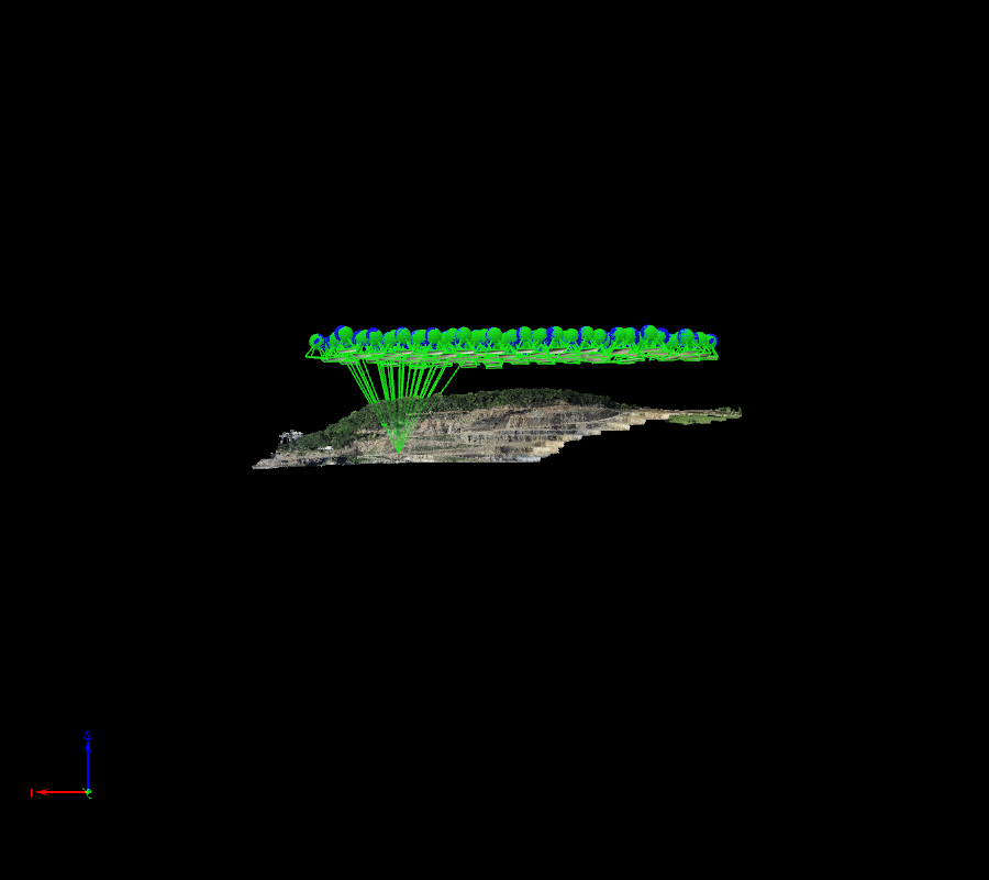
- Back: Moves the viewpoint in such a way that the layers are viewed from the back and fits all the layers in the 3D View.
- Left: Moves the viewpoint in such a way that the view looks towards the left part of the layers and fits all the layers in the 3D View.
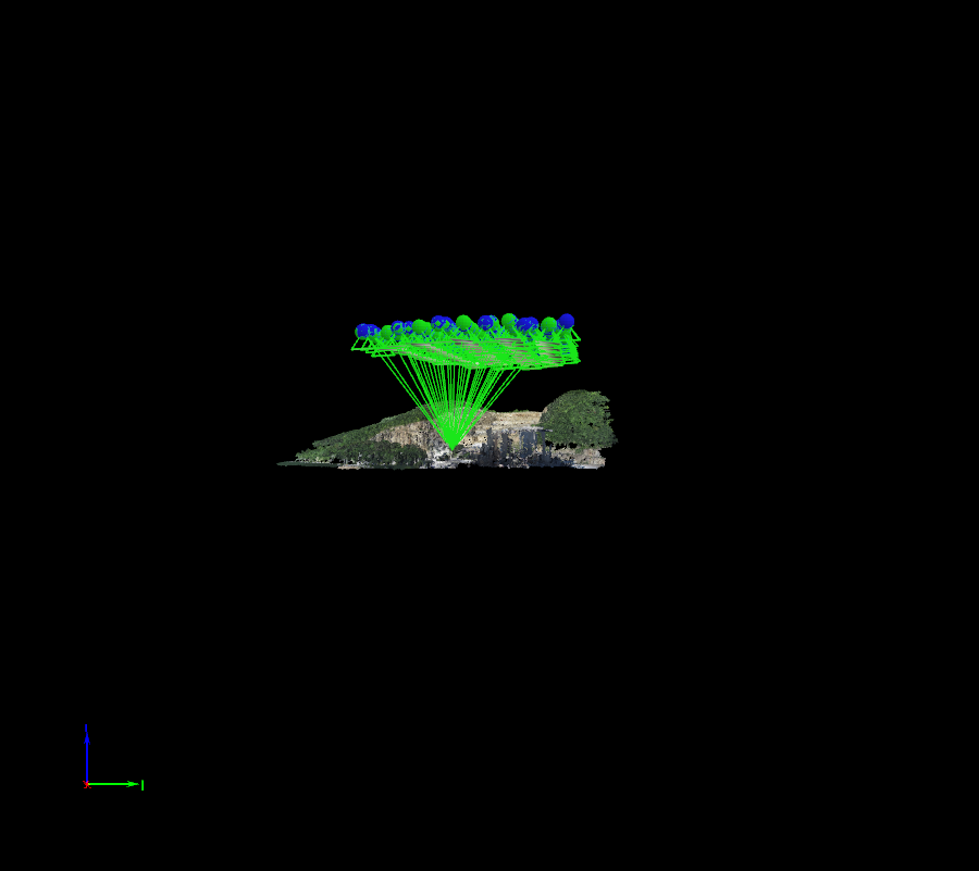
- Right: Moves the viewpoint in such a way that the view looks towards the right of the layers and fits all the layers in the 3D View.
- Home: Moves the viewpoint to the default viewpoint when opening the rayCloud and fits all the layers in the 3D View.
- View All: Press "C" to move the viewpoint in order to fit all the layers in the 3D View.
- Focus on Selection: Press "F" to move the viewpoint in order to display in detail the selected element (point, camera)
- Top: Press "7" to move the viewpoint in such a way that the layers are viewed from the top and fit in the 3D View.
- Front: Press "1" to move the viewpoint in such a way that the layers are viewed from the front and fit in the 3D View.
- Back: Press "Ctrl" + "1" to move the viewpoint in such a way that the layers are viewed from the back and fit in the 3D View.
- Left: Press "3" to move the viewpoint in such a way that the layers are viewed from the left and fit in the 3D View.
- Right: Press "Ctrl" + "3" to move the viewpoint in such a way that the layers are viewed from the right and fit in the 3D View.
- Home: Press "0" to move the viewpoint to the default viewpoint when opening the rayCloud and fits all the layers in the 3D View.
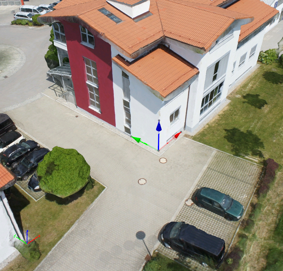
Allows the user to change the way to navigate in the 3D View, which defines how the 3D view reacts when using the mouse or keyboard:
- Standard: Pix4D standard navigation mode.
- Trackball: The camera movements are defined relatively to a ball placed at the center of the view. Recommended to efficiently navigate around a single centered object.
- First Person: Allows the user to interact with the view by simulating piloting the camera rather than manipulating the model. Recommended for close inspection and complex models requiring more degrees of freedom.
For more information and a full description of all the possible actions to navigate in the 3D View using the mouse or keyboard: How to navigate in the 3D View in the rayCloud and the Volumes View.
Defines the projection used to display the layers in the 3D View. By default, the perspective projection is used. It is possible to switch between perspective and orthographic projection by clicking on the Perspective/Orthographic option of the rayCloud Menu bar or the Volumes Menu bar.
It is also possible to change the view type from perspective to orthographic using the keyboard by pressing "5".
- Perspective projection: Parallel lines don't look parallel and further objects appear smaller. This is what human eyes see.
- Orthographic projection: Parallel lines stay parallel. Therefore the size of objects does not depend on the distance. This view mode is recommended for technical drawing.
For more information about Perspective/Orthographic projections:
Allows the user to change the color of the background in the 3D View.
The Select Color pop up appears:
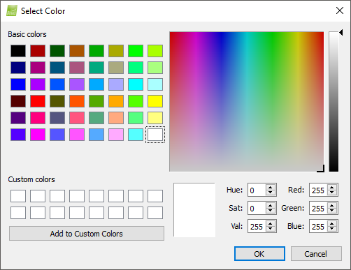
The Select Color pop-up has the following sections:
- Basic colors: Selects a basic color.
- Palette: Selects / modifies a color using the palette.
- Color Properties Values: Modifies a color typing the color properties values (Hue, Sat, Val, Red, Green, Blue).
- Display of the selected color.
- Add to custom colors: Adds the selected color to custom colors, available for other projects.
And the action buttons:
- OK: Confirms the changes.
- Cancel: Does not save the changes.
Allows the user to display a realistic sky gradient in the horizon of the plane where the project is based.
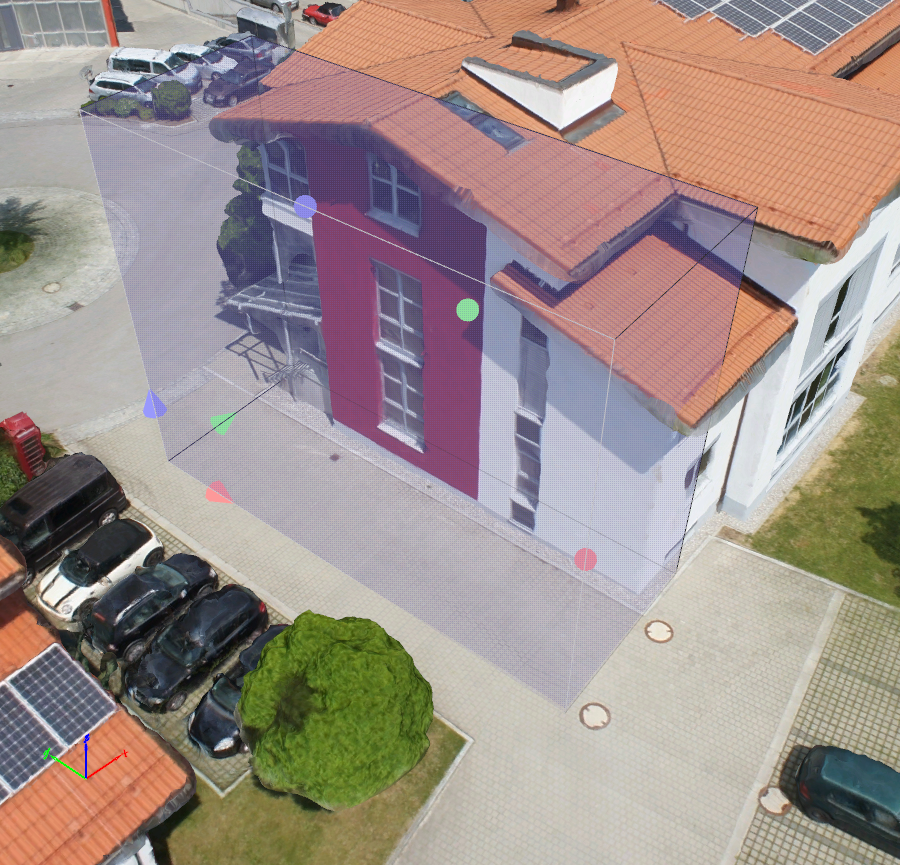
A Processing Area is an area that restricts the model displayed and/or the outputs generated. Only one Processing Area can be drawn/imported in the project. If a Processing Area already exists, the option New Processing Area is grayed out.
For more information about the Processing Area: Menu View > rayCloud > Left sidebar > Layers > Processing Area.
For step by step instructions on how to draw a Processing Area: How to select / draw the Processing Area.
Once a new Processing Area is created, the right sidebar displays the following information: Menu View > rayCloud > Right sidebar > Processing Area.
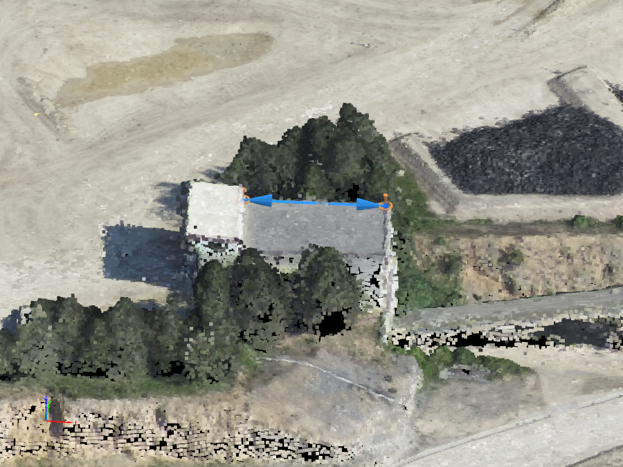
A Scale Constraint is a an line with known real Cartesian distance between 2 points, allowing to set up a local scale of the model.
It is a mathematical constraint over the geometry of the project.
It is used when:
- No GCPs are not being used.
- No good image geolocation is used for the images.
It is used to improve the relative accuracy by adding a local scale to the project, by defining the real distance between 2 known points.
- It is recommended to use the several Scale Constraint and distribute them along the project.
- Once the Scale Constraints objects are added, it is needed to repotimize.
For step by step instructions about how to draw a new Scale Constraint: How to scale a project.
Once a new Scale Constraint is created, the right sidebar displays the following information: Menu View > rayCloud > Right sidebar > Objects.
A Orientation Constraint is a line that represents a known axis, allowing to set up an local orientation of the model.
It is a mathematical constraint over the geometry of the project.
It is used when:
- No GCPs are not being used.
- No good image geolocation is used for the images.
It is used to avoid a rotated model or to force a certain orientation to the model, by defining one or more desired axes (X and /or Y and / or Z).
- In case of using several Orientation Constraint, if they represent a different axis (X, Y, Z), they must be placed with 90o between each other to avoid a deformed model.
- It is possible to create more than one Orientation Constraint for one axis (for example, X), then, the average value will be used.
- Once the Orientation Constraints objects are added, it is needed to repotimize.
For step by step instructions on how to draw a new Scale Constraint: How to orient a project.
Once a new Scale Constraint is created, the right sidebar displays the following information: Menu View > rayCloud > Right sidebar > Objects.
An Orthoplane is a tool to create one or several orthophotos of arbitrary areas of the model without having any impact / modifications in the model.
It is created by defining orthoprojection areas that allows to set up:
- Area of interest (surface and depth).
- Location.
- Orientation and direction of the projection.
- Area of interest (surface and depth).
- Location.
- Orientation and direction of the projection.
Only the geometry inside the box (points of the densified point cloud) will be used to find the projection surface.
For step by step instructions about how to draw a new Scale Constraint: How to draw a new orthoplane.
Once a new Scale Constraint is created, the right sidebar displays the following information: Menu View > rayCloud > Right sidebar > Objects.
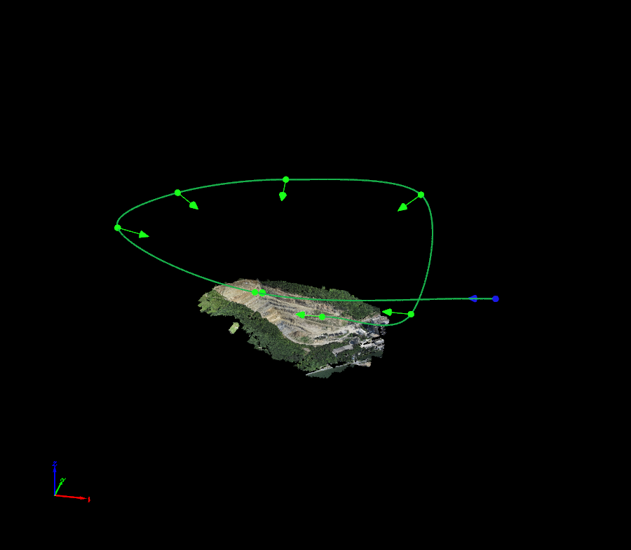
New Video Animation Trajectory
An Animation trajectory is a 3D Fly-trough Animation created as a video.
For step by step instructions about how to create a 3D Fly-trough Animation: How to create a Video Animation Trajectory in the rayCloud.
Once a new Animation Trajectory is created, the right sidebar displays the following information: Menu View > rayCloud > Right sidebar > Objects.
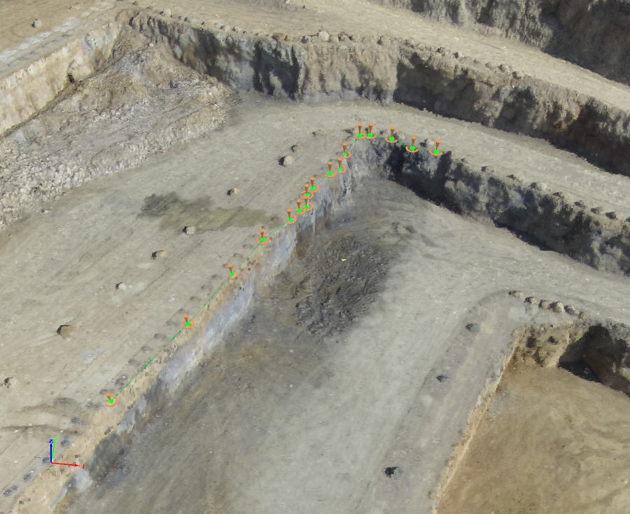
A Polyline Object is a continuous line composed of one or more sub-lines. It is created by specifying the vertices of each line. For more information about the concept of Polylines: What is... (a densified point cloud? an orthomosaic? etc.).
For step by step instructions about how to draw a new Polyline: How to draw a Polyline in the rayCloud.
Once a new Polyline is created, the right sidebar displays the following information: Menu View > rayCloud > Right sidebar > Objects.
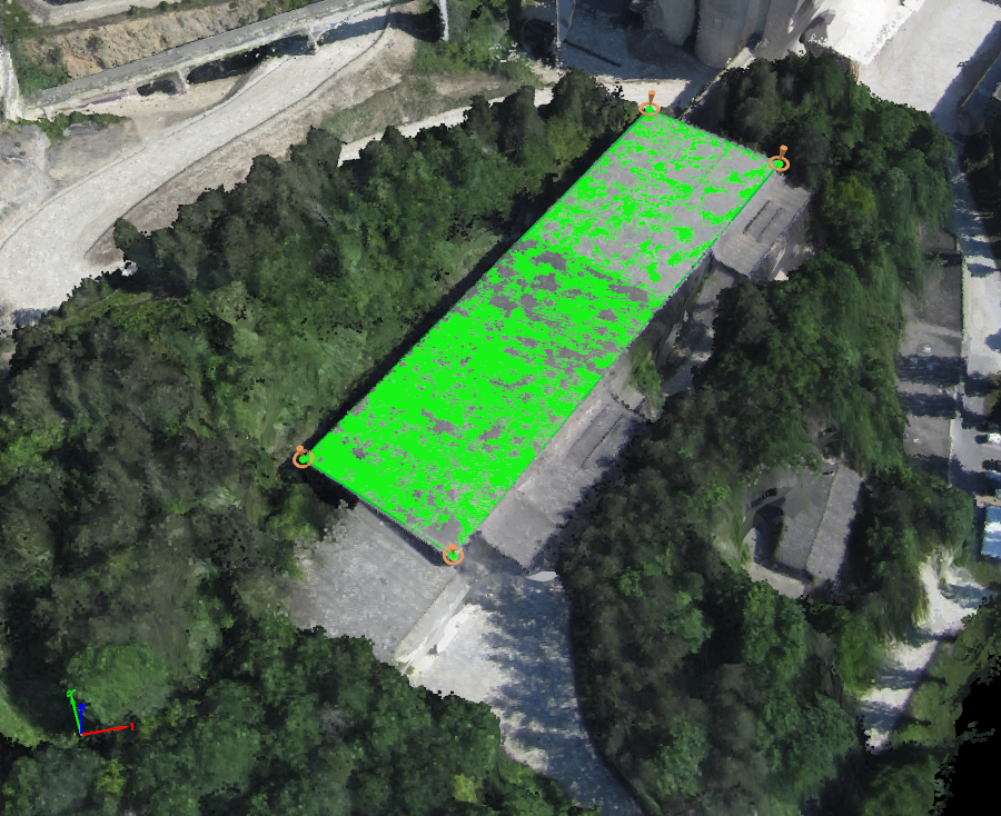
A Surface is an object that can be used to define planar areas such as a road, the roof of a building, etc. It can also be used to correct the DSM and generate a better orthomosaic on these surfaces.
For step by step instructions about how to draw a new Surface: How to draw a Surface in the rayCloud.
Once a new Surface is created, the Sidebar displays following information: Menu View > rayCloud > Right sidebar > Objects.