Access: On the Menu bar, click View > rayCloud to open the rayCloud. The 3D View is displayed in the center of the main window.
The 3D View displays the different objects defined in a project, such as the cameras, the GCPs, etc.The different layers that are displayed in the 3D View and that are also visible in the Layers section of the left sidebar are:
- Cameras: This layer groups all the cameras of the project (calibrated, uncalibrated and disabled). One camera is associated with each image of the project. It is defined by its initial position (if known), the optimized position and orientation.
- Rays: They are displayed when clicking on a 3D point on the 3D View if the Cameras and the Rays layers are shown. The 3D point is projected to all the calibrated cameras in which the point is visible. The rays cut the thumbnails of the cameras at the location where the point is visible in the original images.
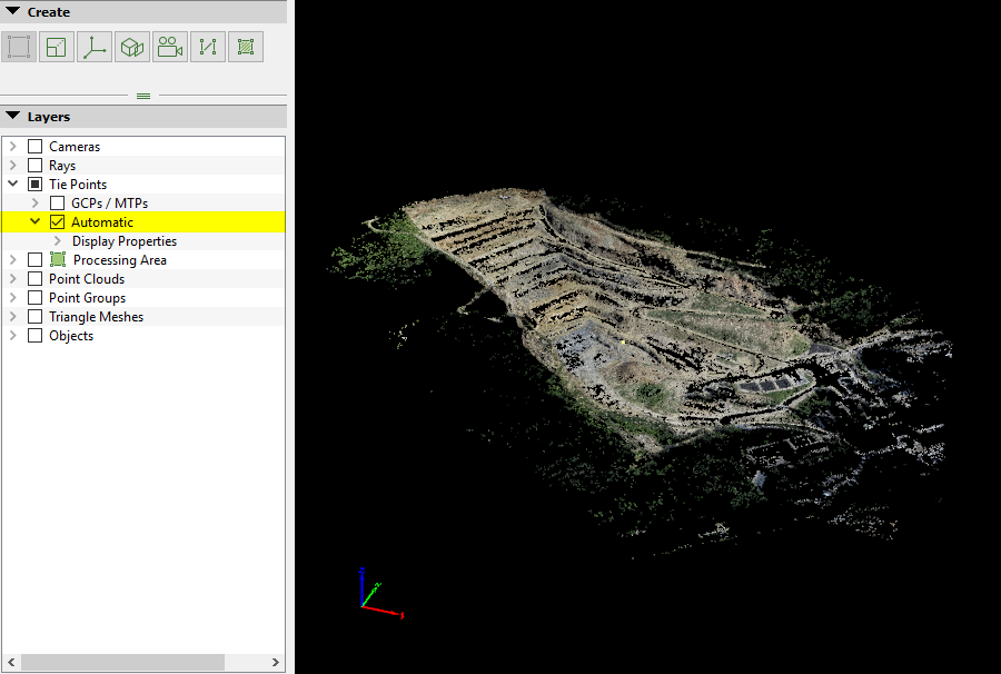
- Tie Points: This layer groups all the Manual Tie Points, GPCs, Check Points, and Automatic Tie Points. The Automatic Tie Points are computed during initial processing.
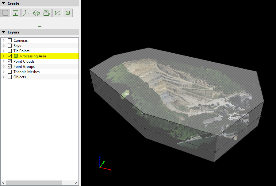
- Processing Area: This layer displays the Processing Area defined in the Map View or the rayCloud.
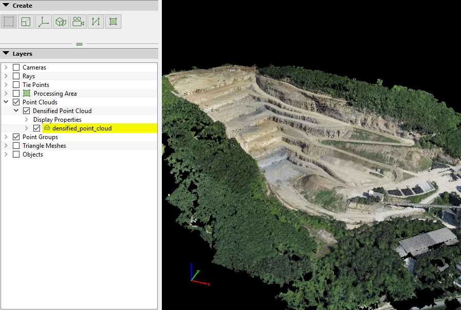
- Point Clouds: This layer groups all the point clouds. It contains the Densified Point Cloud and the drag-and-dropped external point clouds.
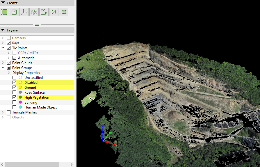
- Point Groups: This layer groups all the point cloud classes. It contains the unclassified group but also all the predefined groups of the point cloud classification and the user-defined groups.
- Triangle Meshes: This layer groups the 3D Textured Mesh and triangle meshes generated by triangulating a point cloud that is loaded as a triangle mesh.
- Objects: This layer groups all the objects defined by the user. These objects can be Polylines, Surfaces, Animation Trajectories, Orthoplanes, Scale Constraints and Orientation Constraints.
- Clipping Box: This tool allows to visualize only the points included in the Clipping Box. This tool is not visible in the Layers section of the left sidebar.
The layers can be shown/hidden using the Layers section of the left sidebar, which can also be used to change the display properties (color, size, etc.) of each layer. For more information about the Layers section of the left sidebar: Menu View > rayCloud > Left sidebar > Layers.
Layers
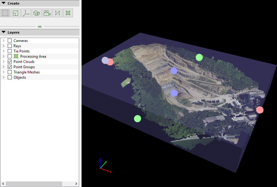
- Blue sphere: Initial camera positions (GPS coordinates).
- Green sphere: Optimized camera positions.
- Red sphere: Initial camera positions (GPS coordinates) for Uncalibrated Cameras for which PIX4Dmapper could not find optimized positions and therefore were not used for the reconstruction.
- Pale Red sphere: Initial camera positions (GPS coordinates) for Uncalibrated Cameras that were disabled by the user and were not used for the reconstruction.
- Green line: Distance between initial and optimized positions.
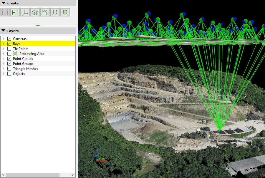
- Green lines: Projection lines between the optimized camera positions and the original image thumbnails.
- Green squares: Borders of the original image thumbnails.

- Green rays: The rays that connect the selected 3D point and the calibrated cameras in which the 3D point was visible but not marked.
- Orange rays: The rays that connect the selected 3D point and the calibrated cameras in which the 3D point was marked.
- Red ray: The rays that connect the selected 3D point and the uncalibrated cameras.
- Light Blue ray: The ray that connects the selected 3D point with the image that is currently selected in the Image View, and on which the point is visible but not marked.
- Light Purple ray: The ray that connects the selected 3D point with the image that is currently selected in the Image View, and on which the point has not been marked.
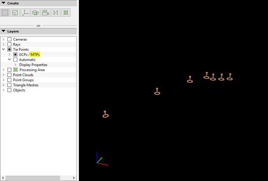
- Green cone: Optimized position of Manual Tie Points, GCPs, Check Points, and vertices of the Objects drawn in the 3D View that are marked in at least 2 images.
- Orange cone: Vertices of the Objects drawn in the 3D View that are marked in less than 2 images.
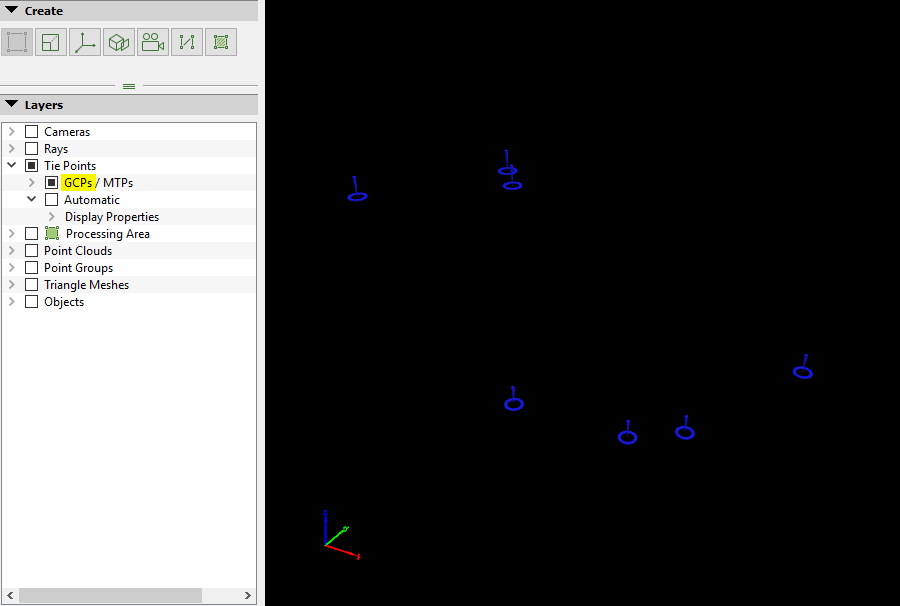
- Blue cone: Original position of GCPs and Check Points.
- Colored point: Automatic tie point computed at step 1. Initial Processing colored using the original images.
- Gray spheres: Vertices of the middle plane of the 3D Processing Area.
- Gray lines: Lines between the vertices of the planes (bottom, middle, and top planes) of the 3D Processing Area.
- Transparent gray planes: Top, bottom, and side planes that form the 3D Processing Area.
- Transparent light gray planes: Top, bottom, and side planes that form the 3D Processing Area when hovering over the area in the 3D View.
- White lines: Lines between the vertices of the planes (bottom, middle, and top planes) of the 3D Processing Area when selecting the area in the 3D View.
The coordinates of a given point are displayed on the bottom right part of the main window when the point is selected in the 3D View.

- For Polylines, Surfaces and Video AnimationTrajectories:
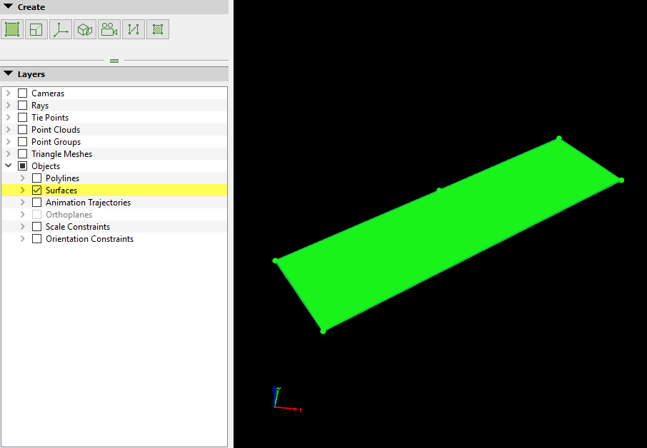
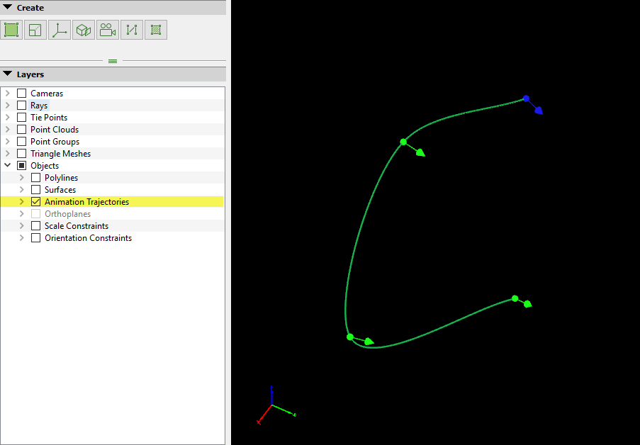
- Green sphere: Object vertices for Polylines and Surfaces. Waypoints for Animation Trajectories.
- Green Arrow: Orientation of the camera in the waypoint (only for Animation Trajectories).
- Blue sphere: First Waypoint in Animation Trajectories (only for Animation Trajectories).
- Blue Arrow: Orientation of the camera in the first waypoint (only for Animation Trajectories).
- Green surface: Base surface for Surfaces.
- Green lines: Lines between vertices/waypoints from the same object. For Polylines, Surfaces and Animation Trajectories.
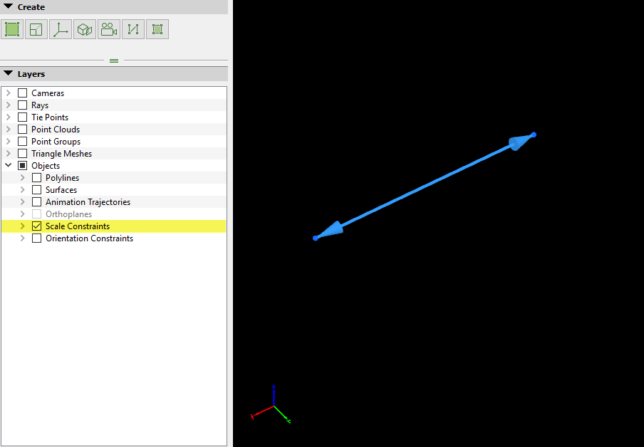
- For Scale Constraints:
- Light Blue double arrow: Scale Constraints.
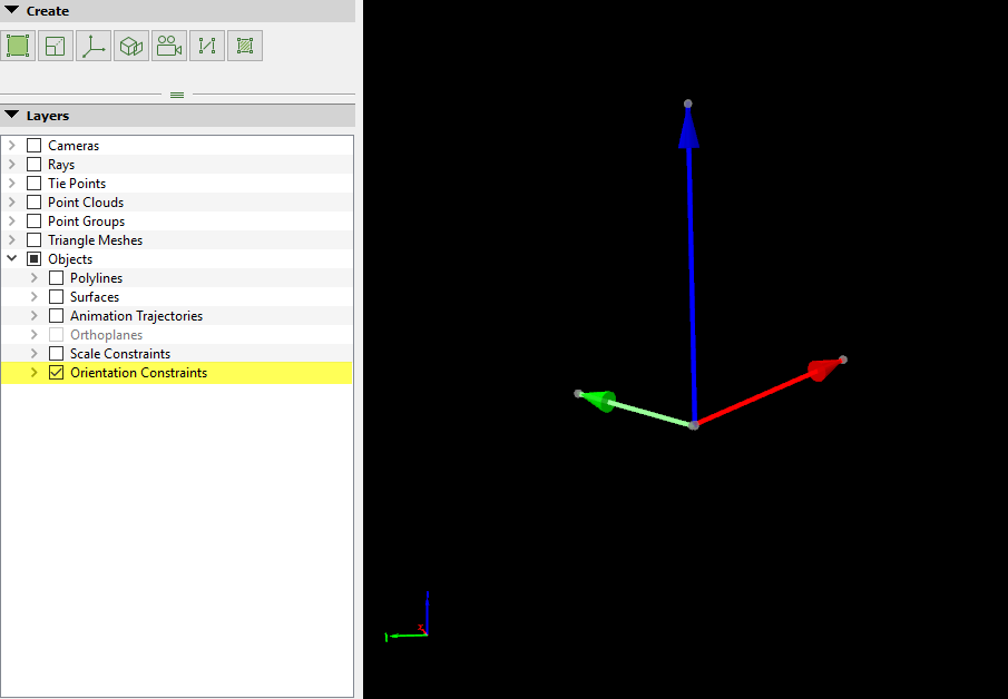
- For Orientation Constraints:
- Dark Blue single arrow: Orientation Constraints.
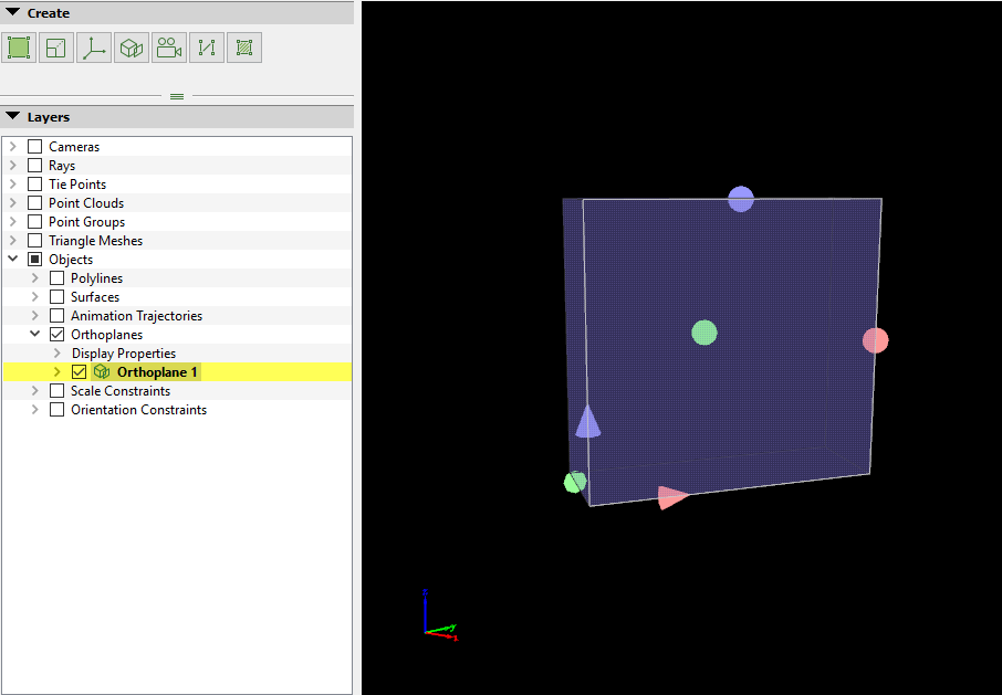
- For Orthoplanes:
- Red sphere: Allows to increase the 3D orthoplane in the X dimension.
- Blue sphere: Allows to increase the 3D orthoplane in the Y dimension.
- Green sphere: Allows to increase the 3D orthoplane in the Z dimension.
- Red cone: Allows to move the 3D orthoplane in the X dimension.
- Blue cone: Allows to move the 3D orthoplane in the Y dimension.
- Green cone: Allows to move the 3D orthoplane in the Z dimension.
- Gray lines: Lines between the vertices of the planes of the 3D orthoplane.
- Light gray lines: Defines the frontal surface of the 3D orthoplane (face that will be mapped).
- Transparent light blue planes: Side planes that form the 3D orthoplane.
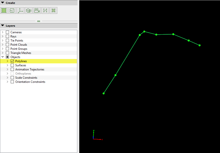 Polylines
- Pink spheres: Allows to increase the 3D area in the X dimension.
- Light blue spheres: Allows to increase the 3D area in the Z dimension.
- Light green spheres: Allows to increase the 3D area in the Y dimension.
- Light purple sphere: Allows to rotate the 3D area.
- Transparent light blue planes: Side planes that form the 3D area.